Table of Contents
ProtoFuse Protodeck
THIS DEVICE IS USED EXCLUSIVELY BY PROTOFUSE AND ISN'T FOR BUYING.
Preambule
The problem is easy to understand: I wanted to drop my PC keyboard + mouse during live performance in order to be focused on music/sound/live.
The only way to solve my problem was to use an hardware to control Ableton Live, but not only that, I need a feedback from it too.
But I need a lot of pots/knobs, a lot of multicolor lights, a lot of buttons…
I need a big hardware without multifunctional knobs, sub-menu you have to choose to change the function of this button etc etc : I need to have ALL under my eyes and I need that EVERYTIME.
I looked for the perfect controller, but I didn't find it. only monochrome stuff or 2/3 colors leds, only few pots with a billion of sub-sub-menu to change encoders function etc.
So, I guess … I have to think, read, code, test, build, learn to solder better… to create my OWN hardware.
As a lot of thing I build/create, I find a name before to begin anything.
A name is important. A name gives you a target. It makes the things more concrete so, the name is: the PROTODECK.
Those who thinks about the so powerful MONODECK II built by Robert Henke by discovering the name could be … right.
By the way, a lot of deck are named like that. But it could be a pretty tribute to Robert, even if he wouldn't be moved by that
By the way (bis), he congratulates me about the hardware. And I was happy about that !!!
Features
THE PROTODECK controller features:
- 87 potentiometers
- 90 buttons
- 81 rgb leds
- 2×20 LCD
- 2 PIC 18F4620 (20MHz RISC processors)
- fully custom rgb led drivers
- fully custom firmware
- 2 MIDI IN/OUT interface
- power supply unit included in the box
I have to thanks a lot of people which helped me A LOT ; without you, this story wouldn't have been possible!
- Denis St Amand:: my quebec friend! he helps me a lot about the structure, screws etc, the PCBs too. he would have helped me with midibox if I didn't do things before to ask him…
- Mike/Noofny :: the guy who made the deltadeck. he inspired me and gave me the power to build the protodeck
- Tim/smashTV :: the guy who makes the very best/reliablest/cheapest midibox modules in the world!
- Lucem :: the guy who helped me about driving a common anode RGB leds matrix
- nILS :: one of the guy connected everytime on old-school IRC midibox channel. thanks you didn't laugh at me (too much) while I asked question…
and obviously, Thorsten Klose, the great midibox creator and guru!
A special thank to Ralf Suckow from Ableton company, for his help, ideas, and experiences.
MIDIbox Framework
The links to favorize right now are:
- ucapps.de / Thorsten Klose website (creator of midibox framework)
- midibox forums
- midibox wiki
- midibox blog
I chose the midibox framework because it is VERY reliable, well documented, it contains a lot of skillful people that contributes to make it evolving.
It could be useful to begin here in order to understand well the purpose.
When you use a framework did like that, you “only” have to code your app. all (hard) things under are already done for you.
This framework is based on hardware and software:
- The hardware part is based on PIC18F series microcontroller + a lot of modules
- The software part is a bootloader + MIOS + my application. A nice schematic here to understand how all these layers go!
There are differents parts which have to be quoted here, even if the read of previous link will give better explanation.
The CORE is the brain. It contains the PIC and all stuff it needs (quartz, midi ports, voltage regulation, etc).
CORE also provides all the input and output for modules connection.
The AIN is a module used when you want to “read a lot of analog voltage”. It can be said differently: if you need more than 8 potentiometers/flex sensors or any other analog sensor, you need it.
Associated with the CORE, it provides 32 analog inputs but can be chained with another AIN and increase the number of input til 64 (or even 128.. crazy stuff!)
The DIN is a module used to read digital input. Basically, it can be used with switches and buttons. You push the button, it reads a value, you release it, it reads another one.
It can be chained too and gives 32, 64 or more digital input.
The DOUT is a module provide digital outputs. It feeds with current or not the devices connected to his pins. The most obvious use in my case was: led control.
It can be chained too and gives 32, 64 or more digital input.
After, I'll describe a big hack I had to do with the DOUT in order to drive my common anode rgb led matrixes. It involves transistor, resistor … a big fun!
All these modules can be built by ourselves or bought as kits. I'll suggest you smashTV website (US). He actually makes the most reliable stuff.. I know what I mean, I tested the others!. He sells preburned PIC.
One of the BIG advantages buying from Tim (smashTV) is the 2×5 pins standard connectors! For each thing, it is the same connector and it is very easy to find self-crimping 2×5 connector part!
The protodeck's code/firmware/apps runs on the core.
I wrote the code using C only. There is a very basic but powerful toolchain in order to compile specifically the C code for this or that processor (mine is a PIC18F4620) Basically, you code, you compile, you upload bytes in the CORE and you test etc. Uploading is very easy and can be done via MIDI sysex using MIOS Studio
There are a lot of applications already coded that we can inspire from.
The principle about to use midibox as a human-machin interface is easy to understand.
it uses midi specifications to translate thing between the real world and the computer world:
- you turn a potentiometer of the protodeck ? it sends midi control change message.
- you push/release a button of the protodeck ? it sends a midi note on/off message.
- you send a midi note message to the protodeck ? it light up a led.
Basic Layout
I need potentiometers, I need buttons and I need feedback from Ableton Live. The feedback is done by RGB LEDS.
I decided to use potentiometers screwed on the frontpanel, and to build my own PCB for buttons & leds.
Firstly, I design a layout that matches with my live set.
I'll add more explicit photos, but for the moment, there is only the following schematics (buttons are square, pots are one-bordered circle, leds are doubled-bordered circle)
Protodeck is : 87 potentiometers + 90 buttons + 87 RGB common anode leds
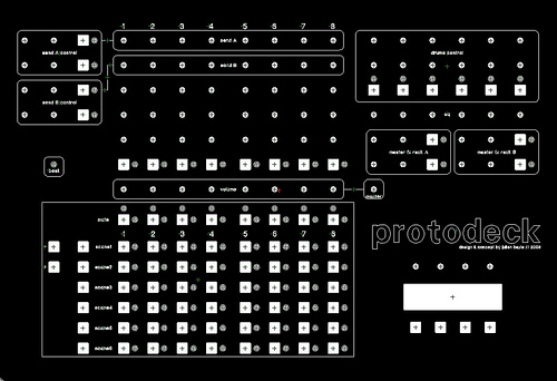
We can see different part in the layout
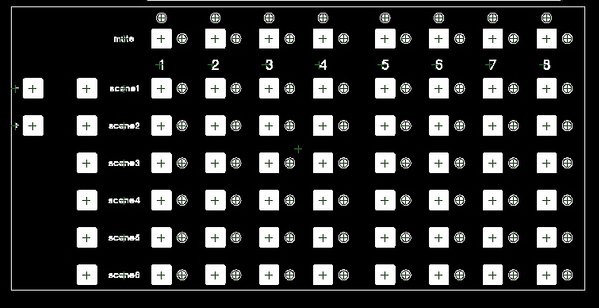
The clip control matrix is used for clip control (!). It involves 64 buttons + 64 RGB leds.
The first row of button mute the track and gives informations about midi note on and the position of cursor of playing clip (beginning, or near to end)
All song are 6 scenes. I can move a little window of 6 scenes with the 2 buttons on the left and the matrix is updated with the content of the live set.
By pushing a button in the matrix itself, a clip is triggered. Leds give feedback of clipslot state (empty, clip playing, clip not playing)
The track control is used for controlling each 8 tracks. 2 pots for send amount, 3 pots for instruments tweaking, 1 button for changing modes or activate a specific FX and the volume pot.
The first track is the main drums track. This drum track is divided in 6 parts controlled by drum control.

The drum control is used for controlling drum tracks. 2 pots for sound tweaking, 1 button for mute each drum part.

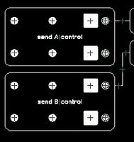
The send control is used for fx rack in send/return track tweaking
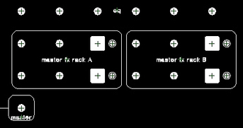
The master control is used for master eq and 2 FX racks tweaking. It contains a master volume pot.
The multipurpose section contains 4 pots, a LCD screen and 4 buttons. This part will be finished later. It will probably provide filter sweep and other pre-programmed variation based on dummy clip stuff
The LCD will be involved in this multipurpose way: it could give a feedback of master volume, showing some important informations like the weather of the next day etc.
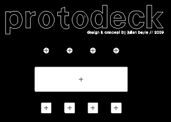
I ordered the frontpanel as soon as I decided the parts I'd use. I ordered it from Schaeffer AG and the result is impressive:

Architecture
Let's go inside protodeck's guts!
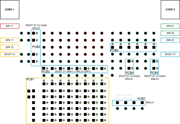
It involves 2 CORE, 3 AIN, 3 DIN, 2 hacked-DOUT, 1 LTC and 1 LCD screen.
All pots, buttons and leds are handled by one modules.
The guts architecture is the following one
I named the modules in order to know which core handles it.
Colors give informations about which module handles which part.
Parts
Potentiometers
Pots of the protodeck are all linear 10K-Ohms potentiometers. Linear is also named “B” type. Don't use logarithmic (“A” type) potentiometers !!
They are multiplexed with AIN modules that involve analog multiplexers (4051). I suggest you, at this point, to read about multiplexer and multiplexing.
But basically, I can say multiplexing is a process where multiple analog message signals or digital data streams are combined into one signal over a shared medium (taken from wikipedia).
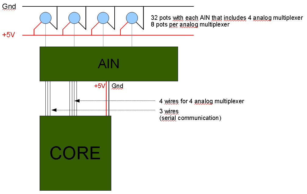
Each AIN can read 32 values and only uses 4 channel. Said differently, 32 pots can be connected to one AIN and only 4 Analog input are used on the core side. It saves analog input.
In the midibox world, pots have only to be fed by 5V/GND and connected to one input of one multiplexer of one AIN. Considering I feed 5v and GND with a star-wiring mode, there is only one wire from each pot to AIN.
Here is the schematic of all the pots wiring. Each “grey triangle” is a flat ribbon cable with 8 wire on the connector side & only 1 on the other side (the side of the last pots in the row) 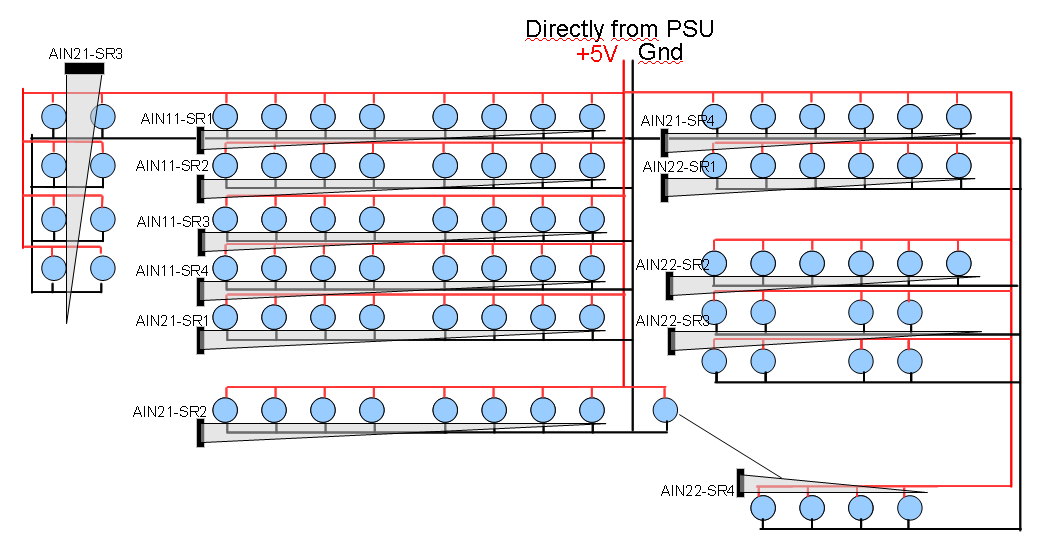
BUTTONS
Buttons of the protodeck are basic SPNO switches (SPNO= Single Pole, Normally Open). It means if you do nothing, the circuit are open, if you push it, the circuit is closed and current rides away.
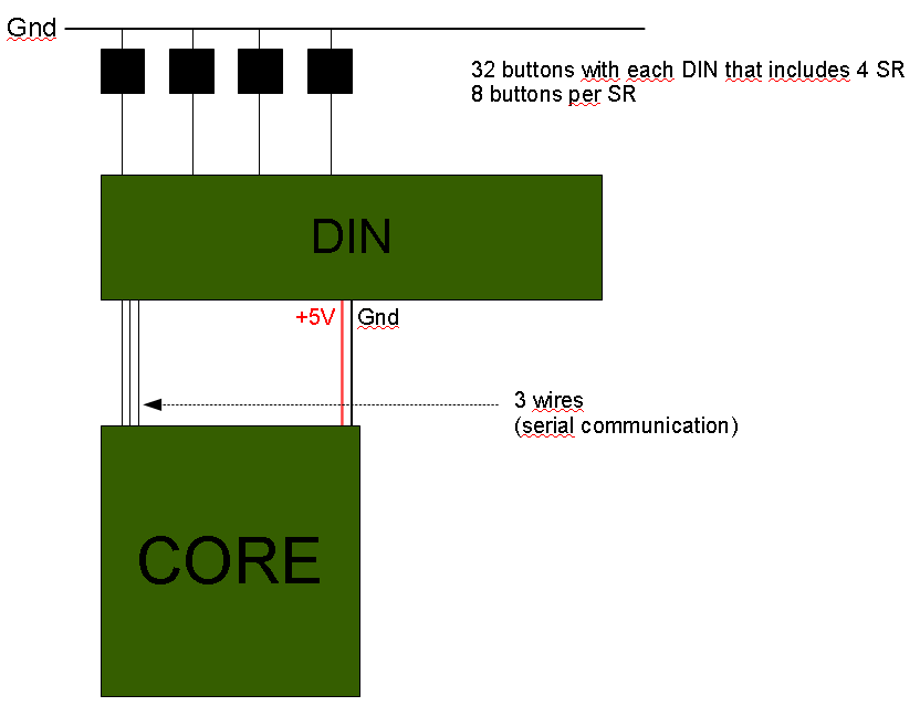
They are multiplexed with DIN modules that involve digital shift-register(SR) (74HC165). I suggest you, at this point, to read about shift register.
Basically, here, in that case, they are said Parallel-IN Serial-OUT: each 8-bit shift-register can read 8 digital input and give the result on 1 serial output.
Each DIN can read 32 values because it involves 4 SR.
With 3 pins involved in the serial communication between DIN & CORE, one DIN can read 32 digital input for the core for which it saves input too.
LEDs
I need RGB Leds like those common cathode or anode we can easily find.
I ordered common cathode, they sent common anode, so I had to hack DOUT module… by the way, I would have to hack that for common cathode too (but a little bit less).
This is the hardest part to figure out cause it involves … code too. I'll describe the hardware principles here and in the next chapter, I'll link it to code/software part.
Basically, I needed 87 RGB LED.
If we consider one led as a common anode, it contains 4 pins:
- 1 cathode for each color (cathode is the pin from which the current goes out)
- 1 common anode (anode is the pin from which the current enters)
If I make a little basic calculation, I needed 87 * 4 pin = 348 pins to drive all the RGB LED. scary!!!
So multiplexing was the way and I built 2 matrixes: one with 8×8 leds, and the other one with around 8×3 leds
- columns = cathodes
- rows = anodes
The resulting number of pins is very reduced:
- 24 pins for columns (= 3 cathodes * 8 columns)
- 8 pins for row (= 1 anode * 8 rows)
This architecture drove me to build the code especially for that:
- all led on a column shared red pin, blue pin & green pin
- all led on a row shared anode pin
The code will have to make a some cycle(s).
I display one row at a time… but very quickly (the row cycling is 1000Hz = 1000 rows displayed per second etc etc). We'll check that in the code further.
Here is a schematic, I comment it further:
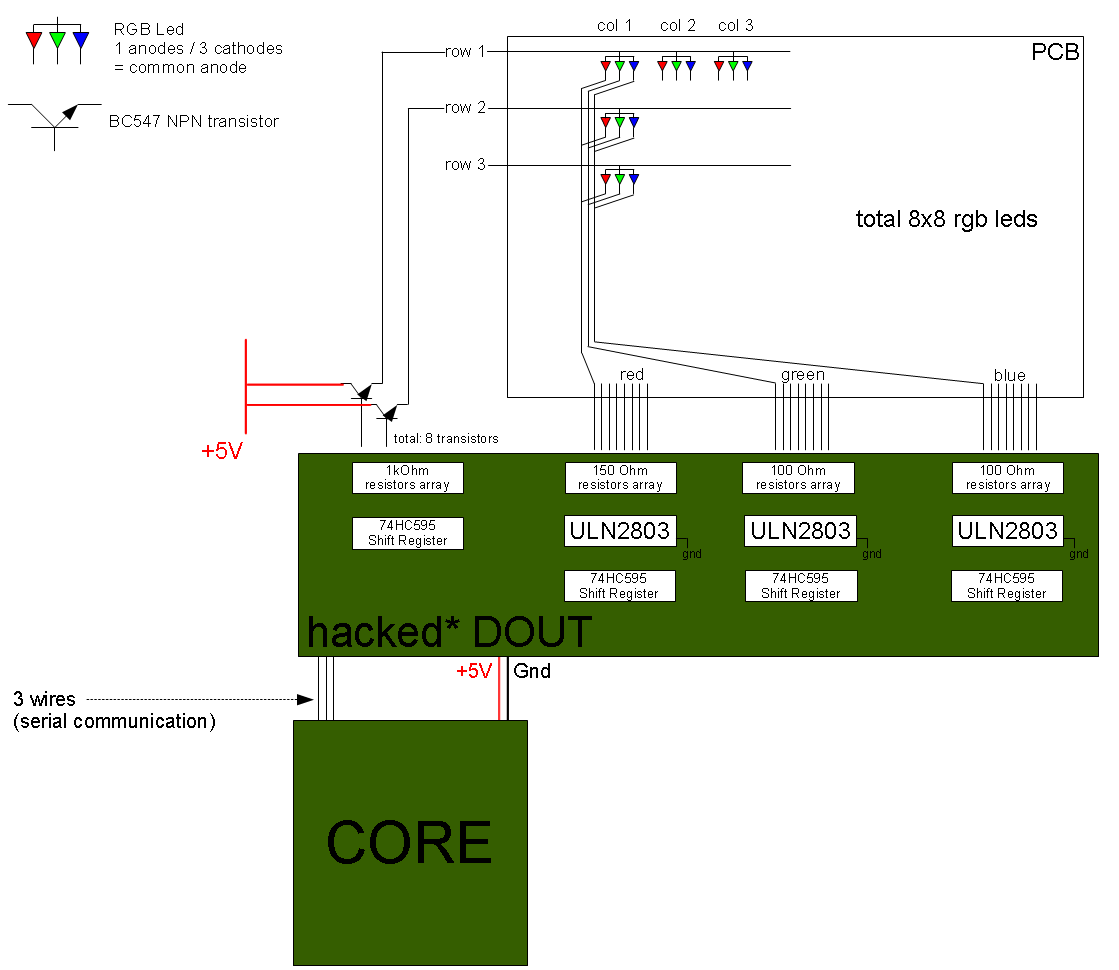
ok. but what does this scary and evil schematic mean about how it goes ???
No problem, I'll explain it.
A RGB led is like 3 little leds in the same package. I'll twist the word led further in order to be faster.
Basically, current comes from 5V line via the BC547 NPN transistor, enters in the matrix by the row, light the led and goes out by columns, sinking by Gnd through ULN2803 Darglinton Array (we'll see that later)
as wrote before:
- in a column, all led of one considered color are connected,
- in a row, all anode are connected
So if I want to light the led of row 1 and column 2 (wrote (2,1)) and the led(1,2), I have to feed the row 1 & 2 with 5v & the column 1 & 2 to ground.
If you followed me, you'd understand that not only led(1,2) & led(2,1) would light up………. but led(1,1) & led(2,2) too !
So when you'll multiplex the hardware, you'll have to multiplex the software to get a complete & correct multiplexing
The principle is very easy to understand.
You send bytes from CORE to DOUT, and the SR in DOUT drives his pin or not (= feed 5V to pins or not).
Because the maximum current a 74HC595 SR can drive isn't enough for a matrix as big as this, we have to use BC547 transistor.
SR feed 5V to base of transistor. This one is saturated and close the circuit between collector and emitter, and let current be driven to row.
So I send 1 to a particular pin of a particular SR, and 5v is available at the emitter of the corresponding transistor. right.
I know how to “send” current to my matrix“. I'll have to make a row cycling in order to avoid to light up all the led in a column when I only want one lighted up. 1st cycle: the row.
Obviously, for closing the circuit, we have to provide a sink way to this current.
ULN28003 is a darlington array component.
Basically, it is linked to ground with one pin (pin number 9) and got 8 input pins and 8 output pins.
You send 5v to input pin N, it connects ouput pin N to ground. Easy to understand. It can be understood as “a kind of” inverter: you send current, it sinks current to ground.
Connected to SR too, it is easy to control them.
ULN2803s sink the column.
At this point, I'm displaying a piece of pseudo code:
for each row r
    feed 5v to pin r of first SR and send 0v to the other (only one row at a time)
    for each column c
        feed 5v to pin c of other SR as you want to light color, composite colors etc.
I guess it is easy to understand (if it isn't, this is probably I didn't explain it clearly enough!)
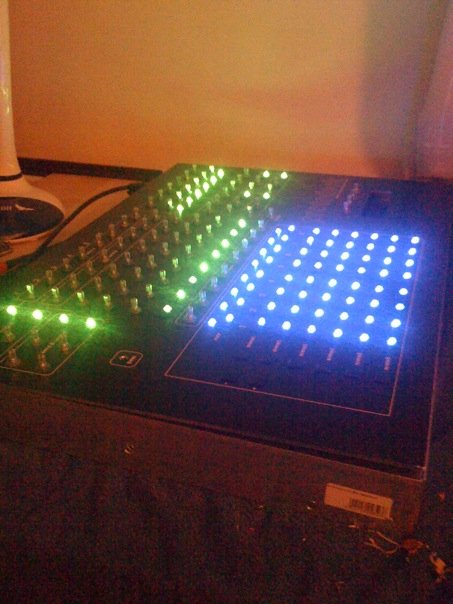
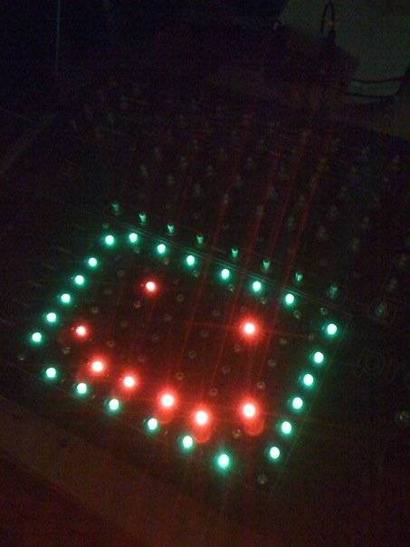
And the leds are ok:
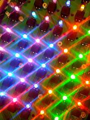
Very awful photos, asap: HIGH QUALITY PHOTO
Printed Circuit Boards (PCB)
I decided to screw pots directly on the frontpanel in order to be sure about solidity when I'd use them.
For buttons and leds, I decided to make my own PCB.
I used Kicad, a VERY reliable “open source (GPL) software for the creation of electronic schematic diagrams and printed circuit board artwork”.
I made all the components with datasheet informations in order to be sure my PCB would fit reality.
I ordered PCB from batchpcb.com. They are in USA, I'm in France. It took around 3-4 weeks. Long time when you're as impatient as me, but a correct delay considering the reliability of PCB you receive at home !!!
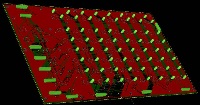
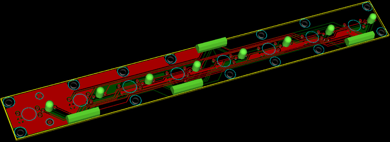
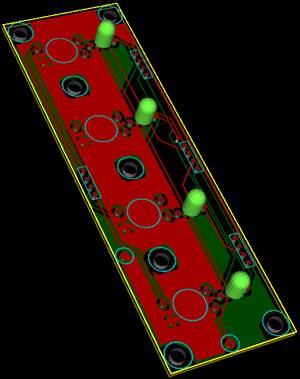
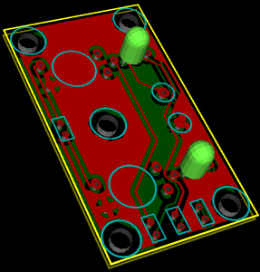
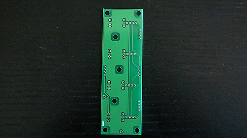
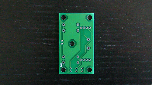
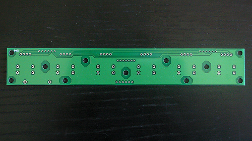
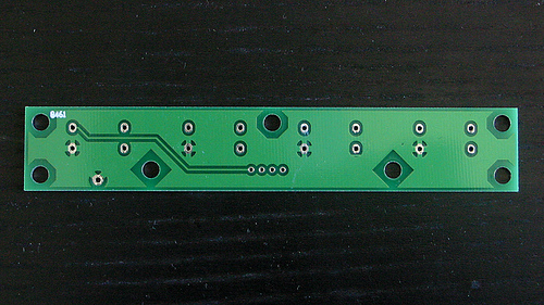
I made 7 PCBs.
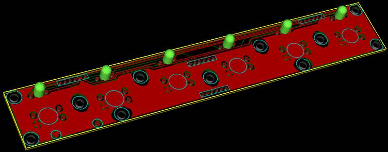
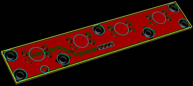
Here are some 3D rendering from Kicad/wings3D in order to see what I expected.
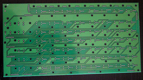
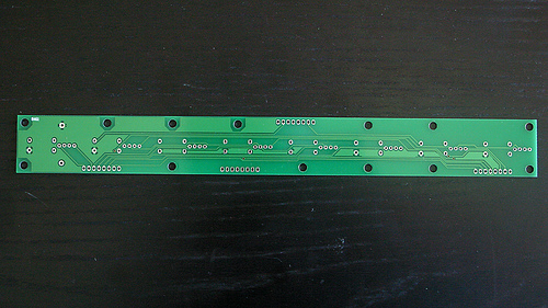
And I received that:
NB: if you checked a bit, you'll find an error. Indeed. and even 2 errors on the big PCB… I had to re-order it in order to get a correctly done PCB.
I put midibox modules at the bottom face and my 7 own PCBs under the frontpanel
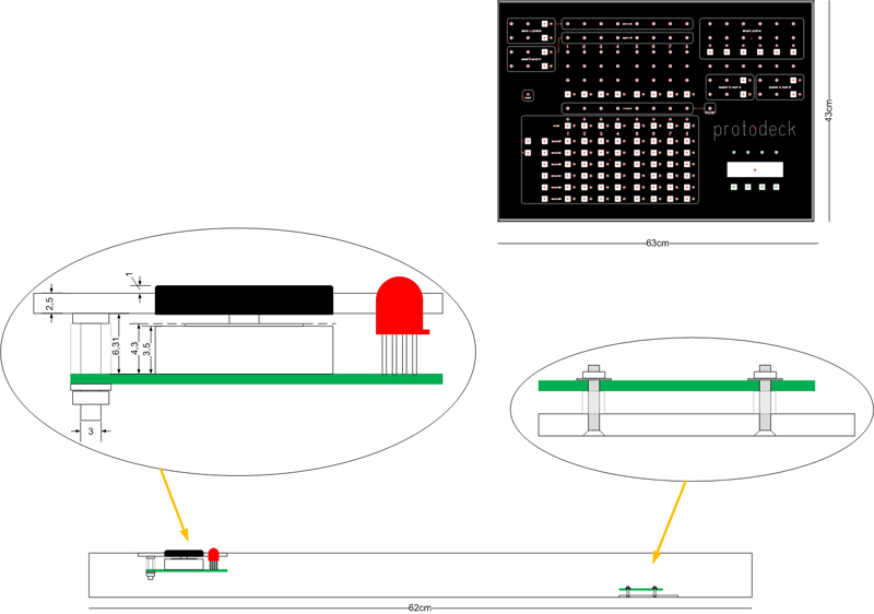
I glued the screws under the frontpanel (Denis St Amand adviced it and … as usual was right!)
I guess I'll modify asap the modules place. Indeed too much cable between the bottom and the frontpanel: it would be better to directly put all modules under the frontpanel, excepted the core at the bottom…
The box was basically made with aluminium corners.
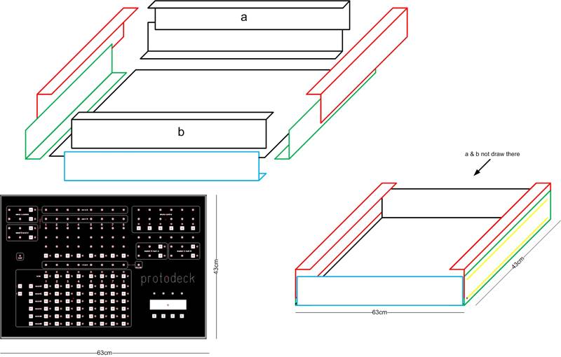
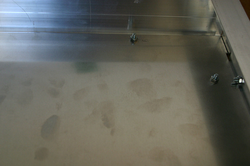
Even if a lot of people thinks I'm a non-finisher-guy, I have to say here that I didn't and won't spend (waste) time to make a perfect box!
Indeed, my way is the music, the code, the design of the interface, not the aesthetic of this box!
“Time is rare, just use it carefully” JB
Firmwares
As we saw before, there are 2 CORE inside the protodeck.
each core runs a particular code especially made for each function he has to provide.
there are 3 specific files per core:
- main.c
- main.h
- protodeck.h
as every C code, it comes with a Makefile file.
The right way to get all of these file is to go there:
svnmios.midibox.org official repository
.
At this point, you should read a bit more about MIDI.
The basic wikipedia definition can be enough here.
How the differents events & messages go ?
Basisally, each core send and receive midi message.
An event handler manages reactions it has to have in case of midi message incoming from the midi input: it can react by acting on his outputs (DOUT, AOUT if there was that is not the case here)
Other handles manage the different inputs (DIN, AIN etc) and reacts by sending midi message to the midi ouput.
The “only” thing you have to do is a mapping between physical components (potentiometers, buttons, leds) and midi messages.
Potentiometers
I had to map each potentiometer to a special midi message called Control Changes.
These messages are made with 3 bytes:
- the status that says they are Control Change messages: 0xb0 to 0xbF (0 means control change on channel 1, F on channel 16)
- the control number: from 0x00 to 0x7F (in decimal, from 0 to 127)
- the value: from 0x00 to 0x7F (in decimal, from 0 to 127)
each pot maps with a control number.
always the same channel (1) is used ; so the second byte is always 0xb0.
the value is the value read directly on the pot (via AIN which has this job!)
Buttons
I had to map each button to a special midi message called Note On.
These messages are made with 3 bytes:
- the status that says they are Note On messages: 0x90 to 0x9F (0 means control change on channel 1, F on channel 16)
- the note number : from 0x00 to 0x7F (in decimal, from 0 to 127)
- the velocity: from 0x00 to 0x7F (in decimal, from 0 to 127)
each pot maps with a note number.
always the same channel (1) is used ; so the second byte is always 0x90.
if I push a button, a Note On message is fired with a velocity of 7F (maximum)
If I release this button, a Note Off message is fired with a velocity of 00 (minimum)
LEDS
I had to map each rgb led to the Note On message too.
each led maps with a note number.
always the same channel (1) is used ; so the second byte is always 0x90.
Velocity codes the led color like that:
// 0x00 = OFF
// 0x10 = RED
// 0x20 = GREEN
// 0x40 = BLUE
// 0x30 = RED + GREEN = YELLOW
// 0x60= GREEN + BLUE = CYAN
// 0x50 = RED + BLUE = MAGENTA
// 0x70 = WHITE
The midi link concept is a midibox framework concept easy to understand.
His main purpose is to avoid midi feedback in multiple core environment.
It is very clearly explained here.
So each message received by the midibox are transmitted to all the core, and each core can transmit midi messages.
The challenge was to avoid that one button connected to the core1 can fire message that could be understood by core2. This was solved by using if() statements and the most nice mapping I found. (the little sign “no way” on the schematic means that if() statements stopped message that mustn't be parsed by core2.
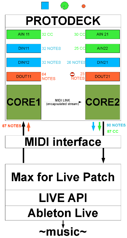
The MIDI mapping is hardcoded in the firmware in order to make it very fast.
Here is a sample of the file I used to make it.

I let you read the code and the different USER functions involved inside.
Interface w/ Ableton Live: MAX4live
Features
- mapping between pots and multiple parameters of the liveset
- mapping between buttons and multiple parameters of the liveset
- mapping between multiple parameters and rgb leds of the protodeck
- full integrated clip control with JavaScript
- full feedback from clips state to leds
- automatic chain selection for automatic instruments change mapped with the current song playing
- midi notes feedback for observing each track midi activities
- send/return ratio control for each tracks
- send/return channel fx racks control
- beat feedback
- fx control |
Max For Live provides “power and modularity of Max/MSP/Jitter directly inside Ableton Live”
The dream became true when Ableton and Cycling 74' announced together this great collaboration 01/2009.
As I was a private beta tester for the software Max For Live, I began to work on it at the beginning of the private beta test session (early september 2009)
Informations about Max For Live can be read there:
- Cycling 74' website
- Ableton website
The protodeck only talk MIDI language with the external world… and it is very enough.
As seen before, it responds to midi note on by lighting LED, it sends midi notes when I push a button and send MIDI CC values when I'm turning a pots. cool.
Now, I need to talk with Ableton Live.
This will be done with Max For Live.
The Max for Live patch I use as an interface is the brain.
All the logic of my live performance are inside of it.
Of course, using it as-it would be stupid. It only fits with my live set, with the protodeck and with my mind.
Of course, parts can be used/altered/adapted for your own use.
It could be a nice way to understand what you can do with max, Max For Live & Live.
First, the live set.\\
The live set (part 1: pictures)
Here is the whole live set.
I first show some pictures, informations/explanations will come after them.
protofuse's liveset part 1 on Vimeo.
The whole set:
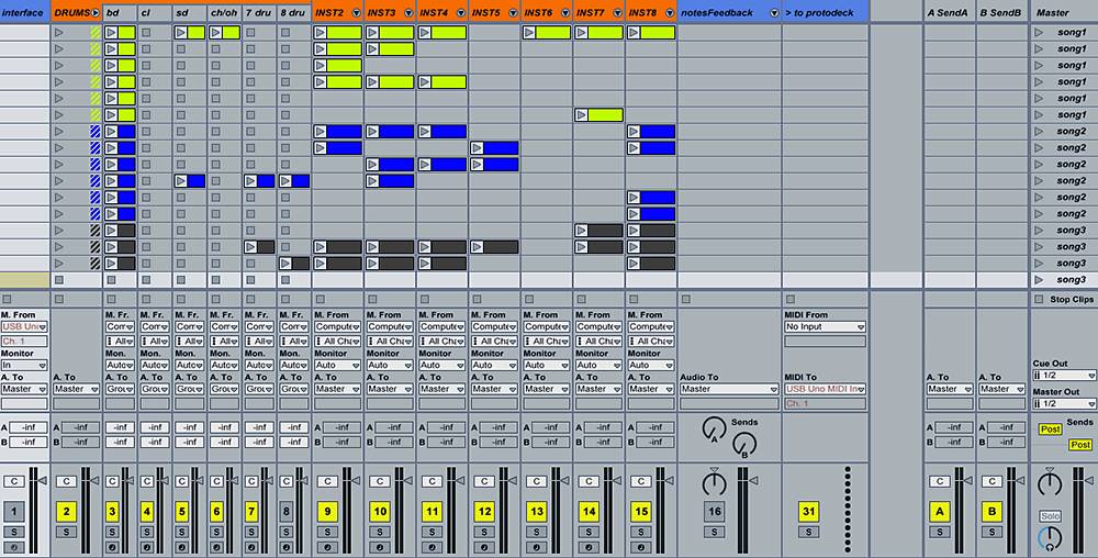
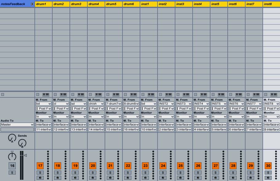
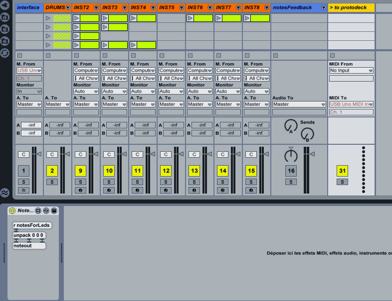
Here is the notes feedback group track deployed:
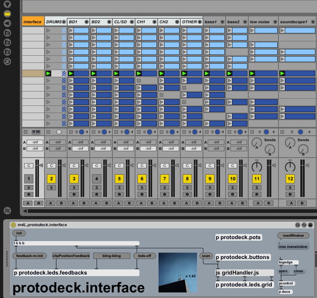
Here is the first track part, where the big interface brain patch sits:
Here is the last track part, where all the MIDI messages targeted for the protodeck go through:
The live set (part 2: words/logic/need)
The whole main tracks are 8 tracks.
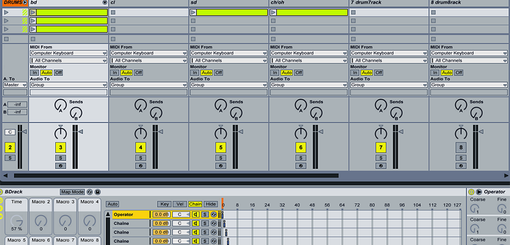
The first is the Drums section. It is basically a group track with 6 sub-tracks inside.
There are 2 send/return channels.
One liveset = One performance = a set of songs
A song = 6 scenes
Each track, excepted the Drums section, contains an instrument rack with chains. Each chain corresponds with a song.
The sub-tracks in the Drums section are like the other tracks: an instrument rack inside, with chains:
Each send/return contains an FX rack with 2 chains corresponding with 2 set of effects.
The max for live logic is basic in my patch:
- all the midi messages from the protodeck comes inside the track 0 where the interface patch sits.
- all the “internal” midi messages which have to be handled by the interface patch go to the track 0 too.
- all the messages from the computer to the protodeck are sent using send/receive objects in max (send is inside the patch in track 0, receive is inside a little patch in the last track (shown before)
Now, I'll describe all the patches inside the interface patch.
I try to be as clear as possible.
If you don't know max, it could be hard to understand, but I try to make you understand though! (what a nice guy I am)
The root level
This is the higher level of abstraction of this patch.

The root level is divided in subpatches:
- protodeck.buttons handles the press/release buttons events
- protodeck.pots handles the potentiometers events
- gridHandle.js is a javascript that handles the clip control part of the protodeck
- protodeck.leds.feedbacks handles the state of FX (on or off), the midi notes feedback and other features that need to be updated constantly and visualized on the rgb leds
- protodeck.leds.grid handles the state of thergb leds of the clip control grid
PROTODECK.POTS (handling of potentiometers)
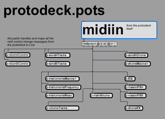
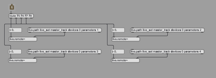
Here I map control changes midi messages from the protodeck to the Live through the API.
First, I'm selecting all control changes midi messages from the channel 1 in order to save cpu time…
After that, I send the selected flow to a lot of sub-patches.
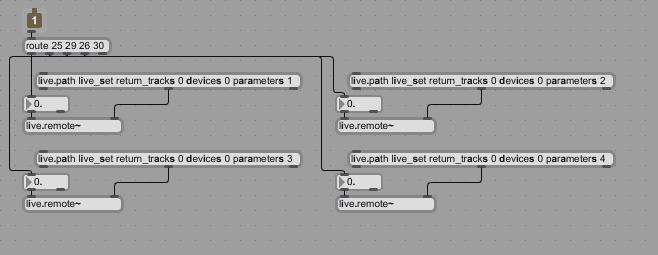
The live.remote~ object is the one most used!
Indeed, it provides a signal rate control instead of using the live.object + set values message that permit automation and thus undo level…
Live.remote~ blocks mouse tweaking, but is the one to be used for hardware controller use.
[p returnAControl] & [p returnBControl] subpatches
Here, I mapped macro 1, 2, 3 & 4 of the rack inside each return tracks.
[p sendATracks] & [p sendBTracks] subpatches
These patches controls the rate of each track audio signal sent to the 2 return tracks.

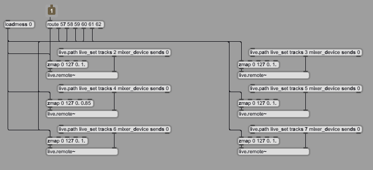
[p sendADrums] subpatch
These patches controls the rate of each drum track audio signal sent to the 1st return track.
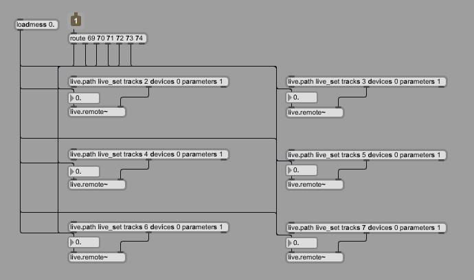
[p drumsMacros1] subpatch
These patches controls the macro 1 of each rack in each drum track.
[p EQ] subpatch
This patcs controls an EQ8 on the master.

[p drumsFX] subpatch
All the drum tracks are inside a group track.
I put 3 racks with an fx in each rack. check it:

The patch maps potentiometers with one macro per rack.
Each macro controls more than one parameter.

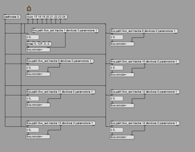
[p instrumentsMacros1] subpatch
In each track, a rack with an instrument in each chain.
One pots in each track controls the first macro of each rack.
PROTODECK.BUTTONS (handling of buttons)
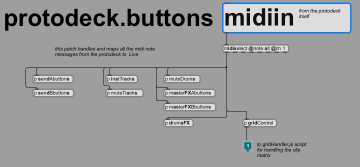
Here I map midi notes messages from the protodeck to the Live through the API.
First, I'm selecting all midi notes messages from the channel 1 in order to save cpu time…
After that, I send the selected flow to a lot of sub-patches.
[p sendAbuttons] & [p sendBbuttons] subpatches
This patch is interesting and is used for [p sendBbuttons] & [p mastFXAbuttons] & [p mastFXBbuttons] subpatches.
The concept is easy to understand: I have racks with 2 & 3 chains inside forsend A, send B & 2 differents racks in the master section.
Look at these :

when the chain selector is:
- 0 means no FX
- 1 means the signal is processed by the chain 1
- 8 means the signal is processed by the 2 chains
- 16 means the signal is processed by the chain 2
The following patch mapped 2 buttons to this behaviour.
I push the first button, the chain 1 processes the signal.
I push the second button, the chain 2 processes the signal.
and the 2 other case (no button pressed, or the 2 buttons pressed)
This is a toggle behaviour: I push/release, it is enabled. I repush/release, it is disabled.
This concept/behaviour is all the same for [p sendAbuttons] & [p sendBbuttons] & [p mastFXAbuttons] & [p mastFXBbuttons] subpatches.
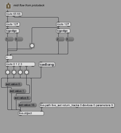
[p instTracks] subpatch
This patch activates/deactivates the autofilter in a track.
Each track includes an autofilter.

[p muteTracks] subpatch
This patch basically mutes/unmutes each track.

[p muteDrums] subpatch
This patch basically mutes/unmutes each drum track.

[p masterFXA] & [p masterFXB] subpatches
This patch works with the same concept than [p sendAbuttons] & [p sendBbuttons]

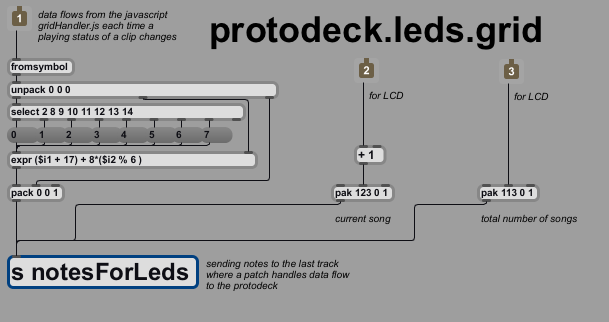
PROTODECK.LEDS.GRID patch
It handles the clip grid feedback
PROTODECK.LEDS.FEEDBACKS patch

This one handles all the leds feedback, excepted the clip grid feedback (see below with the JS system)
Each sub-patch observes things and much more.
The fx state observer sub-patches
Let's begin by those FX states ( sendAState, sendBState, masterAState & masterBState works all the same)
The tip used here is the same the one explained before about controlling FX status… (of course)
I light on/off some leds and it is made automatically when status change.
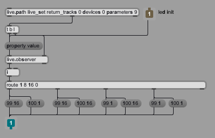
[p instruments] (observing the filter on/off status in each track)
It observes the state of basic filter in each track.
On = led green, Off = led off
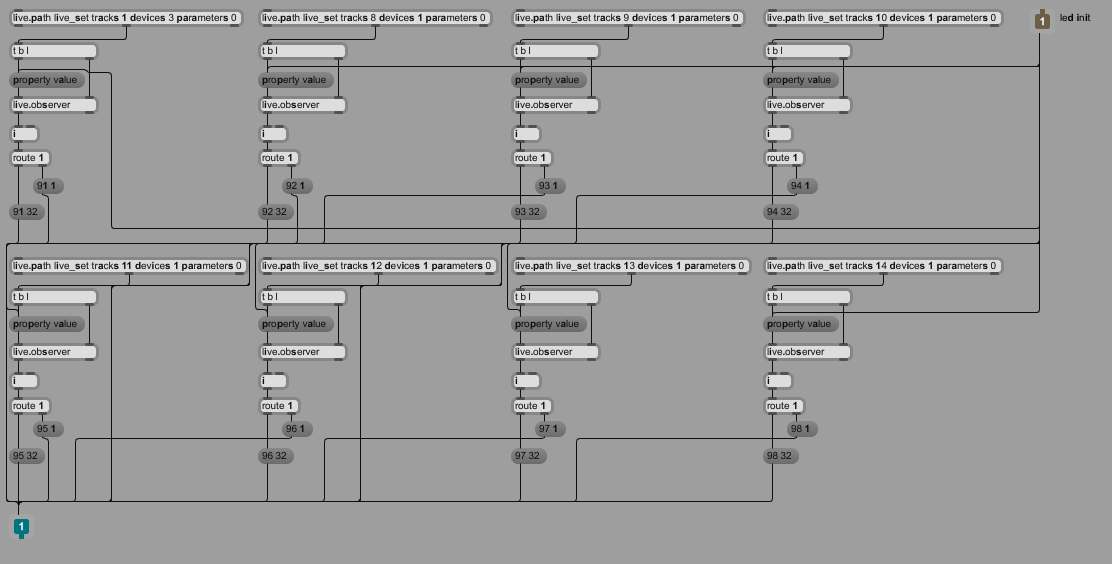
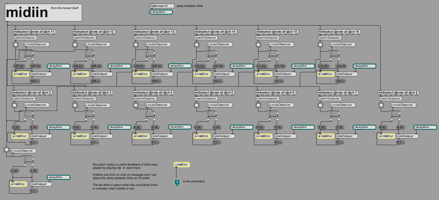
[p midiNotesFeedback] (feedback of each midi notes in each track)
If a note is played in one track, a little green blink occurs.
If the track is muted, but a clip is playing notes, these blink are red in order to make me know the track is playing but muted.
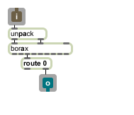
The noteDetector is a basic abstraction I created to fit my need.
The point is the workaround I used with those dummy tracks only used for routing inside the patch (see before)
The noteDetector is:
The blinking feature SHOULD be implemented in the protodeck firmware.
I didn't do that even if I have the C code.
Time is only for music at this moment so … let go there: soundcloud.com/protofuse
héhé, it was an hidden ads!
[p christmas] (only for making fans happy)
It tranforms the protodeck in a pretty christmas tree.
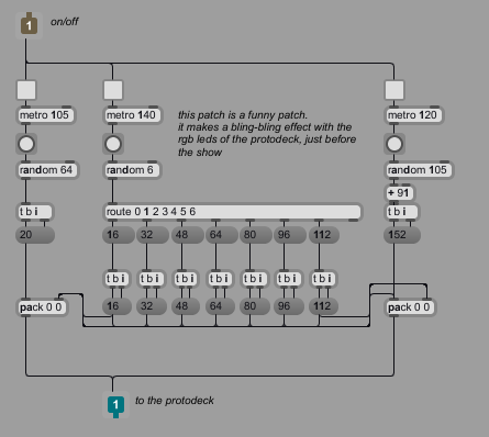
[p allLedsOff] (clear all the leds matrices)
It is a good example about what to put in the firmware (HARD) or in the patch (SOFT)
if I'd want to put that on the software side, I'd need one message midi note per led to switch off all leds………..
I'd prefer to save my midi link, and use a basic firmware clear triggered by only one message (= one per matrix = 2 messages to clear all the protodeck)

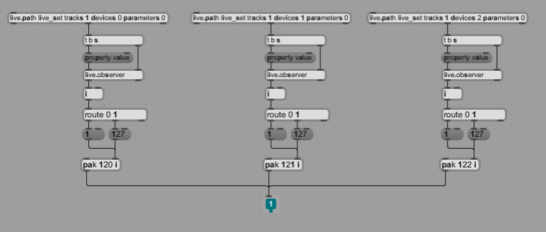
[p drumsFXforLCD] (feedback for LCD)
Here is the drumFXforLCD patch
It observes drum group 3 FX.
A note with a velocity of 1 means the considered FX is off, 127 means on.
The firmware can translate it in a special character on the LCD.
Cool, isn't it ?
Javascript for making music
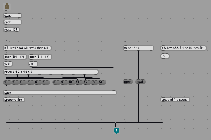
The [p gridControl]
This patch map buttons from clip grid on the protodeck to the javascript code.
It sends messages directly to the script.
These messages are:
- triggering a clip
- triggering scene
- moving the 8×6 protodeck observing grid up or down inside the liveset
/*
/////////////////////////////////////////////////////////////////////////////

Javascript Live API remote controller and Live set follower

20Objects LLC
20Objects.com
Written by
Andrew Pask        andrew@20Objects.com
Darwin Grosse     ddg@20Objects.com


Deeply tweaked for specific protodeck usage
Julien Bayle    julien.bayle@gmail.com AKA protofuse

//////////////////////////////////////////////////////////////////////////////
*/

autowatch = 1;
outlets = 3;

const GRID_X_SIZE = 8;
const GRID_Y_SIZE = 6;

var scene = 0;
var num_scenes;
var num_tracks = 15;
var notePitch;

clip_slot_grid = new Array();
liveset_scenes = new Array();
clip_grid = new Array();

///////////////   Set up arrays and observe tracks and scenes in the Live set   /////////////////
function set_up()
 {

    scene_observer = new LiveAPI(this.patcher, "live_set");
    if (!scene_observer)
    {
        post("no api object","\n");
    }

    num_scenes = scene_observer.getcount("scenes");
    for (y = 0; y < num_scenes; y++)
    {
        liveset_scenes[y] = new LiveAPI(this.patcher, "live_set scenes " + y);
        if (!liveset_scenes[y])
        {
            post("no api object","\n");
        }
    }

    for (x = 0; x < num_tracks; x++)
    {
        clip_grid[x] = new Array();
        clip_slot_grid[x] = new Array();
    }

    scanALL();

     outlet(1, 0);     // current initial song is 1
     outlet(2, num_scenes / GRID_Y_SIZE);     // fire the total number of songs
}


function bang()
{
    set_up();
}

////////////////  Create has_clip observers for each clip_slot fro the WHOLE live_set  ////////////////
function scanALL()
 {
    for (x = 0; x < 15; x++)
    {
        for (y = 0; y < num_scenes ; y++)
        {
            if (!clip_slot_grid[x][y])
            // don't need to create them if they already exist
            {
                clip_slot_grid[x][y] = new LiveAPI(this.patcher, device_callback, "live_set", "tracks", x, "clip_slots", y);
                if (!clip_slot_grid[x][y])
                {
                    post("no api object","\n");
                }
                clip_slot_grid[x][y].track = x;
                clip_slot_grid[x][y].slot = y;
                clip_slot_grid[x][y].property = "has_clip";

                clip_grid[x][y] = new LiveAPI(this.patcher, device_callback, "live_set", "tracks", x, "clip_slots", y, "clip");
                if (!clip_grid[x][y])
                {
                    post("no api object","\n");
                }
                clip_grid[x][y].track = x;
                clip_grid[x][y].slot = y;
                clip_grid[x][y].property = "playing_status";

            }
        }
    }
}


////////////////////////  Forging midi bytes for the current song for protodeck updates  ////////////////////
function output_midi()
 {
    for (x = 2; x < 15 ; x++)
    {
        if ( (x==2 || (x>=8 && x<=14)) )
        {
            for (y = scene; y < GRID_Y_SIZE + scene; y++)
            {
                if (clip_slot_grid[x][y].get("has_clip") == 1)
                {
                    if (clip_grid[x][y].get("is_playing") == 1)
                    {
                      outlet(0, x + " " + y + " 32");     // green  for  clip playing

                    }
                    else if (clip_grid[x][y].get("is_triggered") == 1)
                    {
                        outlet(0, x + " " + y + " 48");     // yellow for  clip triggered
                    }
                    else
                    {
                       if (clip_grid[x][y].name == "R")  outlet(0, x + " " + y + " 80");    // purple for clip not playing & containing a rythm
                       else outlet(0, x + " " + y + " 64");    // blue  for  clip not playing
                    }
                }
                else
                {
                    outlet(0, x + " " + y + " 1");     // off  for  empty clipslot
                }
            }
        }
    }
}


////////////////////////////  Scrolling the view around  //////////////////////////////
function next()
 {
    if (scene < (num_scenes - GRID_Y_SIZE))
    {
        scene += GRID_Y_SIZE;
        output_midi();
        outlet(1, scene / GRID_Y_SIZE);     // fire out the current song number for LCD
    }
}

function prev()
 {
    if (scene >= GRID_Y_SIZE)
    {
        scene -= GRID_Y_SIZE;
        output_midi();
        outlet(1, scene / GRID_Y_SIZE);     // fire out the current song number for LCD
    }
}


///////////////////  Handle clip,scene firing and transport calls from cellblock  ///////////////
function fire(x, y)
 {
    if (x == "scene")
    {
        liveset_scenes[y + scene].call("fire");

    }
    else
    {
        if (clip_slot_grid[x][y + scene].get("has_clip") == 1)
        {
            clip_grid[x][y + scene].call("fire");
        }
    }
}


////////////////////  Catch-all callback function  ////////////////////
function device_callback(args)
 {
    switch (args[0])
    {
    case "id":

        //
        break;

        ///////////////// Handle empty clip slot   /////////////////
    case "has_clip":

        var x = this.track ;
        var y = this.slot ;
            if (clip_slot_grid[x][y].get("has_clip") == 0)
            {
                if ( y>= scene && y<scene+GRID_Y_SIZE ) outlet(0, x + " " + y + " 1");
            }
        break;

    ///////////////// Handle changes in clip playing status   /////////////////
    case "playing_status":

        var x = this.track ;
        var y = this.slot ;

        if ( y>= scene && y<scene+GRID_Y_SIZE  && (x==2 || (x>=8 && x<=14)) ) // only fire midi bytes updates for the current observed scene & only for signifiant tracks
            {
                if (clip_slot_grid[x][y].get("has_clip") == 1)
                {
                    if (clip_grid[x][y].get("is_playing") == 1)
                    {
                      outlet(0, x + " " + y + " 32");            // green  for  clip playing
                    }
                    else if (clip_grid[x][y].get("is_triggered") == 1)
                    {
                         outlet(0, x + " " + y + " 48");        // yellow for  clip triggered
                    }
                    else
                    {
                       if (x == 2 && clip_grid[x][y].get("name") == "R")
                       {
                            outlet(0, x + " " + y + " 80");        // purple for clip not playing & containing a rythm
                       }
                       else outlet(0, x + " " + y + " 64");        // blue  for  clip not playing
                    }
                }
                else
                {
                   outlet(0, x + " " + y + " 1");                 // off  for  empty clipslot
                }

            }

        break;
    }
}
gridHandler.js is a javascript code that handles clip triggering and clip playing status observing.
THE TIP FOR COMPOSING & PERFORMING WITH THE SAME LIVE SET WITH & WITHOUT THE HARDWARE
I need to tweak and test the sounds I'm creating at each time.
When I use live.remote~, the parameter mapped is locked and I must use the potentiometer for tweaking it.
The first way was to create a system to send the message id 0 to ALL live.remote. It is a workaround.
I found another workaround simplier (for me)
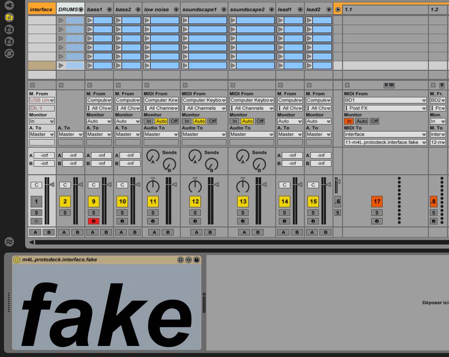
I'm using a fake max for live patch.
Why not removing basically the patch instead of replacing it ??? Because all the routing for note feedback would have to be redone!
So with the fake, I can grab it easily.
I want to compose in the bus/plane, I compose.
I come back home, I plug the protodeck, I replace the fake by the real one. I test the song.
I go to bed, I replace by the fake, I test etc etc
It works. It is simple. I like it!
LCD Screen
I need to visualize the state of the 3 drums FX (no led for that on the protodeck)
I need to know what is the current song (and the total number of song)
I would need other informations too like some level in dB info etc.
I decided to add a LCD screen to the core 2

The most interesting thing isn't the LCD itself or the interface with the core.
It is the high-level part of the protocol I use.
For instance, to update the song number to the protodeck, I send a little midi note message with a defined pitch (here: 123) & as velocity, the song number.
At init time, I send the number of song by sending another special midi note.

