Table of Contents
Make Encoders out of your mouse
Disclaimer
The following manipulation has been tested on a logitech M-M35 mouse, with a “rev C” PCB. There is no guarantee that it will work with other revisions of the PCB, and even less with other models.
The content of this page is given to you “as is”. I am not giving you any guarantee of any kind. It is the result of a single test and it doesn't mean that it will work the same for you.
Abstract
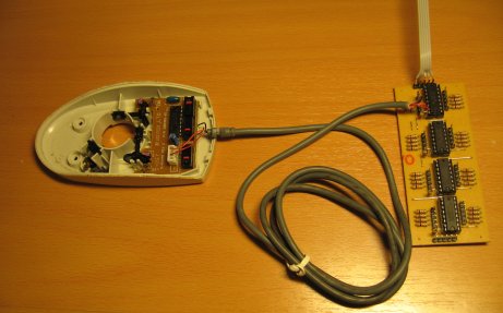
This page focuses on the electronical side of the encoder. It will show you how to connect the PCB of a logitech M-M35 mouse to a DIN.
Connections
The following manipulation will let you use ONE of the encoder.
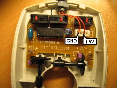
The mouse needs to be powered by a 5V source. On the picture below, the orange cable (left cable) is the 0V (GND) and the red one(right cable) is the +5V. You can either remove the female connector and solder your cables on the male connector or (like I did) use the original connector.
I have removed the other two cables from the connector to use them for the signals of the phototransistors.
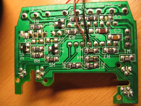
On the other side of the PCB you need to solder the two cables that will receive the signals from the phototransistors, as shown on the picture below. This will let you use the encoder that's on the left on the picture above (on the right on the picture below).
If you want to use the other encoder, you'll need to connect two more cables next to the brown and black cables, at their left (not tested yet).
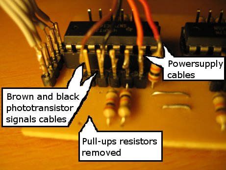
On the DIN board, you'll need to remove the pull-ups resistors, because the phototransistors signals cables already output a stable voltage (either 0V or approx. 5V). I haven't tested with the pull-ups resistors on, but I think it won't work, because the mouse PCB works with very low currents.
Now connect the other ends of the cables to the DIN board as shown below. The red cable (+5V) is connected to the upper part of the resistor. It isn't very nice, but it works…
It isn't a problem if you switch the brown and black cables. It will only switch your encoder's counting (ie turning it right will increase values instead of decreasing them).
Other informations
Observations on the operation of the mouse
The IR LED is powered by very short current peaks (PWM)
The two IR phototransistors are integrated into one chip. When turning the coded wheel, a 0V is measured on one pin, a 4.8V on a second a pin, and two shifted square signals (0V-4.8V) on the two other pins.


