This is an old revision of the document!
Table of Contents
MB-LRE8x2CS PCB / 16 LEDrings/Encoders Control Surface
Welcome to the wiki page of the control surface board featuring combo DINx4 and improved DOUTx4 modules with 16 LEDrings and 16 encoders.
You can find the tread of the PCB design here.
The last revision of the PCB is rev 2.5.
It is a very practical and cheap way to make a midi controller with adding only a core or make a more important controller without having to wire LEDrings.
PCB
The PCB have components soldered on the two sides.
Top side: Encoders and LEDs.
Back side: All others components (see BOM below).
The PCB is two sides white silkscreened on green FR4 material, 1.6mm thickness, 1Oz copper, HASL, 100% E-tested & ROHS compliant.
The board is 3,368 x 13,472 inch (342,2mm x 85,5mm): just less than 2U standard.
The diameter of each LEDring is 1,299 inch (33 mm) with the use of 3mm LED.
Pictures
Protoboard (note this is not the last version but has same dimensions and LEDs/Encoders positioning):
 |
 |
 |
 |
 |
Protoboard in action:


Dimensions
 |
You can download a better definition version here.
Layout
 |
You can download a better definition version (without ground surfaces for better visibility) here.
Silkscreen
Schematic
 |
You can download a better definition version here.
Coordinates
The origin (0;0) is the bottom left corner of the board.
LEDs/Encoders
You will find the coordinates of LEDs/Encoders in this files (new version with better accuracy positioning!).
3mm board holes
Coordinates of the six holes (in inch):
| X | Y |
|---|---|
| 0,16 | 0,16 |
| 6,736 | 0,16 |
| 13,312 | 0,16 |
| 0,16 | 3,208 |
| 6,736 | 3,208 |
| 13,312 | 3,208 |
BOM
| Quantity | Device | Parts | REICHELT | MOUSER | Note |
|---|---|---|---|---|---|
| 2 | ULN2803 Transistors Darlington arrays | ULN2803#1, ULN2803#2 | ULN 2803A | 595-ULN2803AN | optional |
| 8 | 10k 6 Pin SIL resistor network | RN3, RN4, RN5, RN6, RN7, RN8, RN9, RN10 | SIL 6-5 10K | 264-10K-RC | |
| 4 | 74HC165 | IC1, IC2, IC3, IC4 | 74HC 165 | 511-M74HC165 | |
| 4 | 74HC595 | SR1, SR2, SR3, SR4 | 74HC 595 | 511-M74HC595 | |
| 8 | Ceramic Cap 100nF=0,1uF “104” | C1, C2, C3, C4, C6, C7, C8, C9 | Z5U-2,5 100n | 80-C412C104K5R | |
| 1 | Polarized Electrolytic Capacitor 100 uF | C5 | rad 100/16 | 140-REA101M1CBK0611P | |
| 2 | 220 Ohm 16 Pin DIL resistor network | RN1, RN2 | - | 652-4116R-1LF-220 | or 16x Resistor 220 Ohm |
| 16 | 220 Ohm metal film resistor | 8 for RN1, 8 for RN2 | METALL 220 | MF1/4DCT52R2200F | Instead the 2 RNs above |
| 2 | 2-row DIL Header (2×5 pins) | “IN”, “OUT” | SL 2X10G 2,54 | 649-67996-420HLF | For Reichelt, buy only 1 item and cut it in 2 parts |
| 1 | 1-row SIL Header (1×16 pins) | “TO_SWITCH_BOARD” | SL 1X36G 2,54 | 649-68001-416HLF | optional |
| 16 | PEC16-4020F-N0024 | ENC1, ENC2, … , ENC16 | - | 652-PEC16-4020FN0024 | Undetended - without build-in switch |
| or | PEC16-4020F-S0024 | - | 652-PEC16-4020FS0024 | Undetended - with build-in switch | |
| 10 | Socket 16 pins | - | GS 16 | 571-1-390261-4 | |
| 2 | Socket 18 pins | - | GS 18 | 571-1-390261-5 | 8 (NOT 9) bridges to solder if not using ULN2803s |
| 256 | LED 3mm or rectangular (2x5x7mm) | LED1, LED2, … ,LED256 | LED 3MM RT | - | Reichelt model recommended |
This is a Mouser Orderlist (Thank you Lamouette). You have only to add your LEDs and Pinheaders.
LED black list
Since Tk discovered a brightness problem with some rectangular 5x2x7mm LEDs, we found it useful to create a list of LEDs wich are successfully or unsuccessfully tested. Members are welcome to edit this page to add their LED feedback.
| Model | Type | Link | Good | Not good | Comment | Author |
| Kingbright WP103HD | 5x2x7mm rectangular | Mouser | X | Tk | ||
| LED 3MM RT | 3mm round | Reichelt | X | Tk | ||
| “10001” | 5x2x7mm rectangular | auspiciousmall.com | X | Fairlightiii | ||
| Kingbright L-934ID | 3mm round | Segor Electronics | X | rvlt |
Components
LEDs & LEDring
Each LEDring is composed of 16 LEDs.
You can use 3mm LEDs or 5x2x7mm rectangular LEDs (because the different angles of the LEDs in the LEDring) or all other LED with 0.1 inch (2,54 mm) leads spacing.
There's not enough space for 5mm LEDs.
 |
The LED polarity: the cathode (short leg) has to show to the center of the LED ring:
 |
Encoder
You can use 16mm “standard” encoders (ALPS STEC16, Bourns PEC16-4xxxF-Nxxxx series, encoders sell by voti, …).
You can use instead PEC16-4xxxF-Sxxxx series (with built-in switch). Probably others built-in switch encoders comply the PCB footprint but you have to compare before datasheets.
16 pins SIL header
If you use switched encoders, one of the two pins of the built-in switch is grounded while the other pin is connected to a pin of this SIL connector.
The silkscreen include the name of each switch.
2x5 pins DIL headers
They are 1:1 with J8/J9 of Core8/Core32/LPC17 so you can use practical IDC female Connector or still more easier pre-built 2x5 Pin IDC Ribbon Cable.
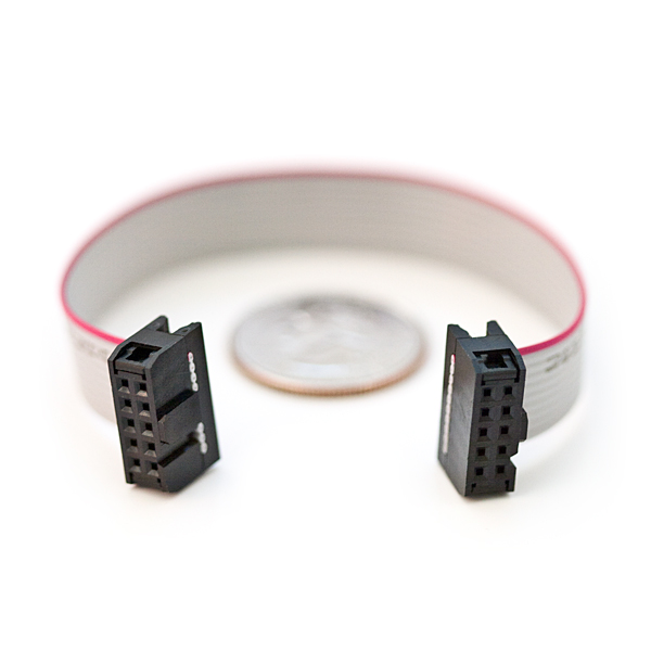
Be careful to the connection to the MBHP_CORE_LPC17 module because it could be confusing, since the SO pin of J8/9 has to be connected to the SI pin of the LRE2x8 board, and SI to the SO pin (for MBHP_DOUT/DIN we usually have the same names for these signals, this detail has been overlooked).
ULN2803
This component provide more current to the matrix LED than the 74HC595 shift registers can and improve the brightness of the LEDs.
You can use or not Transistors Darlington arrays.
In the second case (and only in this case), you need to bridge 16 of the 18 free pins 2 by 2 (in red on the picture):
 |
| Be careful to not bridge the 2 last pins (those opposite to the “head” of the chip). |
 |  |
| An idea is to use e.g. DIP16 Switch. (NT 08 at Reichelt). |
220 Ohm 16 Pin DIL resistor network
As in the SmashTV's PCB, you can replace a DIL resistor network by 8 resistors.
In this case I recommend to use 1% metal film resistors because with the tolerance of standard carbon resistors you could see maybe different brightness of each LED of the LEDring.
10kOhm 6 Pin SIL resistor network
Be careful when sourcing SIL resistor networks because a 6 Pin SIL resistor network can be 5 commoned resistors (what you need here) or 3 independant resistors.
Polarized Electrolytic Capacitor 100 uF
It is the only polarized cap of the board. The silkscreen indicate the “+” and “-” signs on the board.
Diagram interconnection
One board connection
 |
Only one 2×5 Pin IDC Ribbon Cable is necessary to connect the board.
 |
Global interconnection
 |
| You can download a better definition version here. |
You can chain 4 of this board or connect yours extra DIN/DOUT modules e.g. on the DIL connector named “OUT”.
You can connect also this board at the end of the chain and connect this board with the “IN” connector after yours others modules.
With the use of the upcoming MIDIbox NG (planned for Winter 2012/13) you will be able to have 2 chains of 4 boards each (2x4x16=128 encoders and 2x4x16=128 LEDrings).
Whishlist
For an eventual next revision of the PCB, this is a list of improvements that members are free to complete:
- Changing IN/OUT sockets by polarized sockets and improving the silkscreen (to avoid confusing SI/SO pin). Tk
- Moving cap C5 (too close to the IN socket). Tk
- Trying to move some critical vias. Fairlightiii
- What about the use of ULN2803s? Fairlightiii
- Trying to add DINX2 onboard to handle the 16 encoder switches (start/end of the chain?). Fairlightiii
- What about the size of the PCB? Fairlightiii