This is an old revision of the document!
Table of Contents
Questionable's Midibox Projects
History: Several years ago, I started work on an Analogue Modular Synth (still unfinished), which was to include a Midibox Midi→CV component. Like the synth, the Midi→CV was never finished. Recently, I've been getting back into DJ'ing (Traktor) and playing around with visuals (VDMX), and wasn't happy with any of the controllers on the market for those uses. I decided to take another look at creating a Midibox controller, and thus this Traktor project was born.
Elsewhere: I have created a blog that details the construction of this Midibox and other music/video hardware that I'm working on. You can find it at http://www.nonsilence.com
Note: I wouldn't recommend anyone copy my design, part selection, etc, until I have finished the project and have confirmed that it all works. I'll be sure to rename the headline below once I've finished everything.
Another Traktor Controller (Finished and Working!):
My controller is designed to provide controls for the features I use most in Traktor. Because of this, I've left out controls for features that other users might find essential (looping, pitch control, etc). There is also a section of the controller that is specifically for functions in VDMX, and will not be used for Traktor. In addition to the Midibox controller, VDMX is controlled by a DIY Arduinome (Monome http://monome.org/ clone).
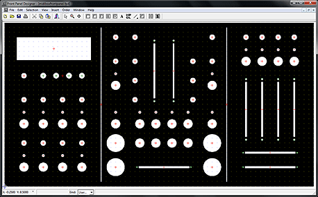
Panel Layout: The first thing to do was the Panel layout, to determine what configuration of Midibox modules I was going to need. I decided to have the panel made by Front Panel Express rather than attempt it myself.
Note: I have realized that this is not the most recent screenshot of the panel layout. You can easily see the differences between this and the finished product.
Left Panel: This portion controls the effects, and houses the display. The buttons directly under the display are the nav, execute, and snap buttons to navigate the menus. There is also a pot directly under the LCD to control the backlight brightness. Below that are two sets of 4 buttons, LED's, and Pots. The buttons control the on/off state of individual parameters in the Traktor effects, while the pots control the variable values. There are two sets of these controls, as there are two main effects busses in the current version of Traktor Pro.
Middle Panel: The middle panel is all Traktor controls. The large buttons on either side of the crossfader are arcade buttons, built for heavy use, that control the play/stop and sync functions. The two vertical faders are volume (no pitch faders for me). Directly to the sides of the volume faders are EQ pots, with filter sweep buttons/pots next to them. Directly under the volume faders are FX 1&2 on/off buttons, one set for each deck. The 8 buttons directly above the crossfader are cue point selections. The three pots at the top of this panel are my headphones, mix, and master volume levels.
Right Panel: The right side of the controller is all generic pots, buttons with LED's, and faders to be used with VDMX for a variety of functions. I swayed heavily towards faders/pots on that side, as my Arduinome has the button issue covered.
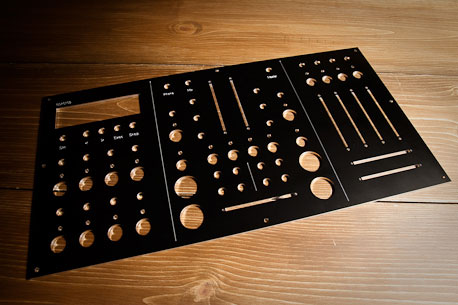
Here is a picture of the finished panel.
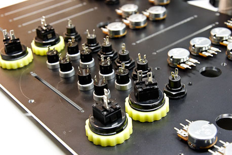
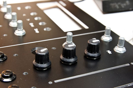
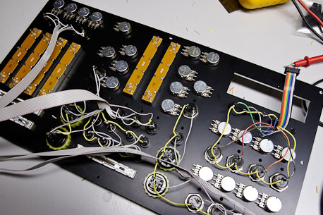
Here are a few pictures of the front panel being populated with pots, faders, buttons, and LED's.
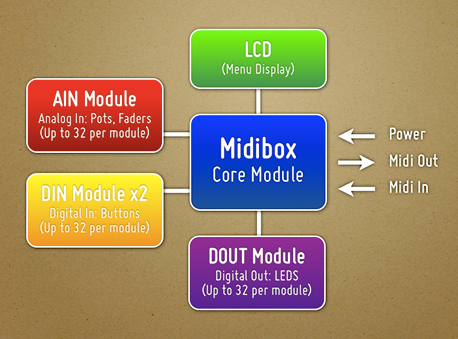
Midibox Module Selection: The final tally of buttons, faders, and LED's is what determines the number and types of modules that you require. Mine is as follows:
- Buttons: 36
- Faders: 9
- Pots: 23
- LED: 20
This means that I will need the following Midibox modules:
Part Selection: As I am in the U.S., I have primarily ordered from U.S. vendors (Mouser, AllElectronics, SmashTV, etc), although several of the parts had to be ordered from other countries when domestic suppliers couldn't be found.
Midibox Modules: All of my Midibox modules have been ordered from SmashTV http://www.avishowtech.com/mbhp/index.html, who is the U.S. supplier of most of the Midibox PCB's. They also carry kits that include all (or most) of the required parts to populate the PCB's, as well as additional odds and ends that you'll probably need as you build your controller.
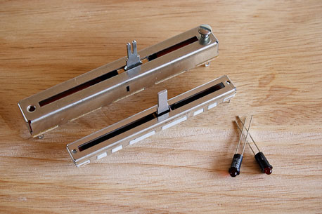
Faders and Fader Caps: I'm using two different types of faders on my Midibox. The first is an Alps fader (Mouser # 688-RS6011YA6009) which is a relatively decent fader, although not terribly light in touch. The second is an Alpha Fader (Mouser # 312-9301F-10K) which is considerably cheaper than the Alps, but not quite as nice. The Alps faders are being used for the 3 crossfaders, while the Alpha's are used for the remaining vertical faders. In retrospect, I might have been better served with faders that have a slightly shorter stem that fits the caps, as mine are a tad bit higher off the faceplate than I had hoped. The caps that I'm using are Neutrik/RE-AN (Mouser # 550-77304), and will work well for the vertical faders, but I am looking for a more DJ style fader cap for the horizontal crossfaders.
Potentiometers and Knobs: The pots I'm using are from Futurlec (POT10K) and are pretty cheap. They've worked well for projects in the past, so I'm hoping that they'll work well for this project as well. The knobs used for the pots are Neutrik/Re-An Soft Touch control knobs (Mouser # 550-67005). They fit the Futurlec/Alpha pots perfectly, and have a nice grippy feel to them.
Buttons: I'm using a variety of buttons for the controller. The large arcade buttons are Seimitsu PS-14-DN 24mm Pushbuttons, available from Lizard Lick Amusements. A few of the buttons were purchased through ebay from a Chinese company (not the best buttons, it turns out). The rest were purchased from All Electronics, including the following part numbers: CAT# MPB-17 (cue point buttons), CAT# PB-159 (menu nav buttons), and CAT# PB-155 (general use black plastic buttons).
Power Supply: I'm using a simple wall wart style box I picked up at a local electronics store. Mine is rated at 9VDC, and 800mA. When you purchase the power supply, be sure to pick up a matching panel mount connector for the box.
I've been trying to take pictures of the parts that I've ordered and received, more can be found over at my blog http://www.nonsilence.com
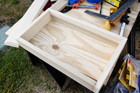
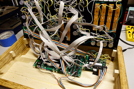
Building the Case: The case is also a DIY job, created from a few pieces of poplar. I have absolutely no woodworking skills, so I'm not at all unhappy with how it turned out, although it's certainly not perfect.
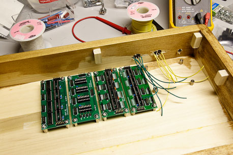
The shot above shows the module PCB's attached, awaiting the core module being hooked up to midi wiring and the power input.
Wiring the Panel: Now comes the tedious and time consuming part of the build, wiring the front panel. For the most part, the PDF diagrams on the ucapps site that accompany each module are the keys to understanding the wiring sequence. I'm using ribbon cable, as it will be easy to attach to the modules, and keeps the overal spaghetti-ness of the panel down considerably.
The shot above shows the DIN (pushbutton) wiring completed. I've left the ribbon cabling long until I can determine how long the runs will need to be to get to the modules.
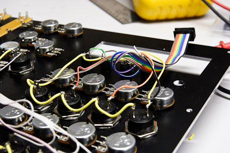
Here's a detail shot of the grounding sequence for the buttons. The black wire on the ribbon cable is connected to the VS pin on the DIN board. The rest go to their individual buttons. The black cable is then daisy-chained from one button to the next (via the yellow, thicker wire) until all of the buttons have been grounded.
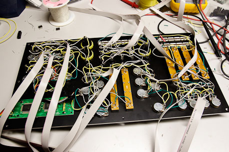
This shot shows all of the panel components wired and ready to attach to the modules.
Problems I encountered:
There were plenty. Most of them my fault. I'm offering these here so that others might not have the same problems.
Ordering the Wrong Fader Taper: Damn. I knew that I needed Linear Faders, not Logarithmic. Still, when I ordered, somehow I ended up with the wrong resistance taper. Do yourself a favor, and double check that your faders/pots are linear before you start wiring them onto the board.
Grounding the AIN Faders and Pots: It says all over the schematics and diagrams that you need to clamp to ground any unused analog inputs. Having 32 faders and pots, I didn't think I had any unused analog inputs (I have only one AIN module), so I was surprised when I was getting random midi traffic once the board was connected to the core. It took me a while to realize that it was the 2nd AIN input pins on the CORE module that were causing the problem. Ground the second set of inputs into the core module (J5B on the core), and that should solve the problem.
DIN Module: For some reason, the SmashTV DIN boards I have weren't working correctly when attached to the core module (ie, my buttons weren't working). This was solved by using the outermost J1 pins, instead of the inside row of pins. Not sure why that is the case, but it worked for me.
DOUT Module: LED's work properly for a short while, then all light up. For me, this was fixed by replacing the ribbon cable IDC connector that interfaced to the board. Not sure what the problem was, but I figured I would start with the easiest things first.
Wire your LED's logically!!!!!: I somehow had it in mind that I could connect the LED's to the DOUT in any way I wanted, then reassign the LED pinning in the software. That's not true. While you can change which shift register is responding to which DIN bank of buttons, you can't reassign the individual LED's. The easiest thing to do is just wire them up properly from the start. What I ended up doing was unplugging all my LED cables from the DOUT board, then turning on the Midibox and hitting buttons while taking voltage readings from the multimeter on different pins on the DOUT. When you hit a DIN button, one of the DOUT pins will send a 5 volt signal. Figure out which pin that is, and then wire the appropriate LED to that pin.
The LCD DIM Pot doesn't work: For whatever reason, the pot I have on the core that is supposed to dim the backlight doesn't work. I don't really care though, as the LCD is at a good level, and I don't think I'll need to change it.
Trouble Doing Sysex Transfers via Vmidibox64: I wanted to customize the button/LED behavior to act as toggled inputs instead of simple on/off (meaning 1 press turns LED on, 2nd press turns LED off), as well as change the default fader/pot labels (Reverb, Chorus, etc) to labels that matched the functions on my box. It seems to be easily done via Serge's Vmidibox64 program, but every time I would then try to do the sysex dump to the midibox, the LCD would start showing bizarre characters, or shift over a few characters. Weird stuff. Eventually, I used Midi-Ox and the mk_syx perl script to create the Sysex file and upload it, which worked perfectly. Details of this process can be found here: http://www.ucapps.de/howto_tools_mbsyx.html
Additional Thoughts and Considerations:
Have your front panel made professionally: It makes a world of difference. I've tried making front panels before, and while it might be passable, it won't be perfect. The panel I got from Front Panel Express is a work of art, and I am extremely happy that I paid the extra money to have that done. When doing so, however, you have to be 110% sure that your measurements are correct. Use the data sheets on your components, don't trust your own measurements. You might also consider having a local carpenter make a nice wooden box to your specs. I didn't, but I might in the future.
Just order the kits: SmashTV has been kind enough to put all of the parts together into kit form. Take advantage of that. Finding all of the parts on your own can be difficult, and it'd be a real drag if some of them didn't work properly, or you ordered the wrong parts.
Consider the usefulness of a shift key: I hadn't thought of it when I started designing the box, but Traktor can make use of a shift (modifier) key, so you should be able to have a number of your buttons do double duty, simply by adding a separate shift button. This could be especially useful if you're using the control surface to select tracks, etc.


