Table of Contents
<box 35% blue right | » MBHP (Insert the matching section here) >
| Content | This article describes the functionality of the DIN-module. This module is part of the MBHP and provides digital inputs to a MidiBox device |
|---|---|
| Additional Info |  This article needs to be reworked (just as an example ;)) This article needs to be reworked (just as an example ;)) |
| Connects to: | J9 on Core8 and Core32 or optionally to J16 or J19 on Core32 (requires additional programming) |
| OS | MIOS8 / MIOS32 (this line can be left out if not necessary) |
| Links | Wiki Links - Links to other pages that are related - More links - even more links External Links - Links to other pages that are related - More links - even more links |
This whole box contains more info about the content of this page. The logo on the right and the color of the box is matching the section the page belongs to </box>
The DIN Module
A DIN module is used to connect buttons and encoders to the Midibox. The Name comes from “Digital Input” and means that the module can detect two states: ON or OFF.
- DIN Module uCApps
Connection to Core Module
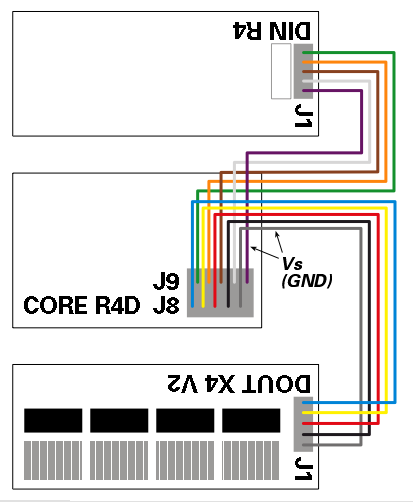
Check the version of your Boards;
if you're using SmashTV's Core that's equipped with double rows, you can build a split-cable to connect J8/J9 to a DIN and a DOUT:
Troubleshooting
Testing all pins
Regardless which MIDIbox you are planning to build, you can use the MIDIO128 application to test the digital inputs of the DIN module(s)
Once MIOS and the MIDIO128 application have been uploaded, each digital input will send a Note On event (pin 1-64) or Controller Event (pin 65-128) when a button is pressed (=0V at the digital input pin), and a Note Off event (pin 1-64) or Controller Event (pin 65-128) when the button is released (=5V at the digital input pin). Rotary encoders will send two Events (because they are connected to two pins) depending on the quadrature state.
Each pin will trigger an individual note/CC number. This is the second byte of a event. The first pin will send “90 30 7F” when pressed, and “90 30 00” when released. The last 128th pin will send “B0 4F 7F” when pressed, and “90 4F 00” when released. The MIDI events can be displayed with MIOS Studio or a MIDI monitor (e.g. MIDI-Ox) The MIDIO_OUT_ENTRY definitions in midio128_presets.inc help to map the pins to the events, the DIN & DOUT Pintable helps to map the pin numbers to shift register pins.
Testing Shift Register Connections
If the first input pin of the first shift register (74HC165) triggers all 128 Notes at once, there is propably a problem with the Shift or Register Clock line (SC/RC signal). Both signals are driven by the core module, and they are connected to all shift registers in order to scan the chain. If these signals are not connected, or if there is a short, the core will always “see” the first digital pin, and never the remaining pins of the chain.
If some of the last shift registers cannot be scanned, it is very likely that the SC/RC line is broken, that there is a bad soldering, or similar.
Such types of errors can be located with the srio_interconnection_test application, which can be found at the MIOS download page. Step by Step instructions for the testing procedure are described in the main.asm file
Check:
- the SC/RC output at the core module (J8/J9)
- the SC/RC input of each DINX4 module (J1/J2)
- the LD/CLK input of each 74HC165 (Pin #1 and Pin #2, see DINX4 schematic)
If you notice a short circuit (signals always 0V or 5V, or between these voltage levels), check the cables between the modules and especially your soldering at the bottom of the PCB. Consider also, that a PCB track could be broken or connected with another track (etching imperfection).
Connect each signle DINX4 module directly to the core in order to find the bad candidate(s).
If visual checks don't help to detect the short circuit, you could begin with a very drastic, but effective method: cut the failing track in the middle, and check if the short has disappeared. Cutting has to be repeated until you've found the cause for the failure.
Warning: Don't do this too early, this should be the last measure which normaly leads to success, but also to a bad looking PCB. After this procedure, you have to repair the track with some solder