Table of Contents
SEQv4+ le mec
This board holds the SEQ's illuminated buttons, which are driven from a shift register matrix. The ENC-PLATE board stacks on top.
Schematic
A shift register chain of 3 DIN 74HC165 and 2 DOUT 74HC595 chips are used. Two of the DINs scan the encoders and one scans the button columns. The DOUT parts are connected into a matrix. Note that both the high and low sides have driver transistors (PNP and NPN, respectively). This means that the anode side of the matrix will operate with inverted behaviour (pin high = LED off). Actually the low (cathode) side is also “inverted,” as we turn the transistor “on” to sink the current by toggling the 595 pin high.
There are special instructions for connecting the parts which are covered below.
BOM v1.0
Please find the current BOM on http://midiphy.com. The table below is depreciated and will not be updated.
| Type | Qty | Value | Package | Parts | Mouser | Reichelt | Conrad | Other | Notes |
|---|---|---|---|---|---|---|---|---|---|
| Resistors | |||||||||
| 1 | wire link | THT | R17 | ||||||
| 16 | 47R 5% | THT | RJ1-8 | see instructions | |||||
| 10 | 100-220R 5% | THT or 1206 | SJ1-8, RJ9 | see instructions | |||||
| 16 | 1k 5% | THT | R1-16 | ||||||
| 8 | 10k 5% | 1206 | R18-25 | near NPN transistors | |||||
| Resistor networks | |||||||||
| 3 | 9*10k | SIP10 | RN1-3 | bussed network, not 5 pairs of resistors | |||||
| Capacitors | |||||||||
| 5 | 100n | 1206 | C1-5 | ||||||
| 0 | do not fit | C6 | |||||||
| Diodes | |||||||||
| 24 | 1N4148 | THT | |||||||
| 24 | BAT54 | SOT-23 | 512-BAT54 | BAT 54 SMD | |||||
| LEDs | |||||||||
| 16 | RGB flat | superflux | ELV: 68-10 94 64 | see instructions | |||||
| 8 | various | 3mm | insert into switches | ||||||
| Transistors | |||||||||
| 8 | BC808 | PNP SO-23 | |||||||
| 8 | BC818 | NPN SO-23 | |||||||
| ICs | |||||||||
| 3 | 74HC165 | SOIC16 | IC1, IC3, IC5 | 595-SN74HC165DR | |||||
| 2 | 74HC595 | SOIC16 | IC2, IC4 | ||||||
| Switches | |||||||||
| 16 | Matias | QuietClick | SW1-16 | see notes | |||||
| 8 | MEC/APEM | 3FTH9 | SW17-24 | 642-3FTH9 | TASTER 3FTH9 | 705276 - 62 | |||
| Headers | |||||||||
| 1 (3) | 1*3 | male | |||||||
| 3 | 1*10 | male | |||||||
| 2 | 2*5 | male | |||||||
| Hardware | |||||||||
| 16 | switchcaps | ALPS-DSA clear | |||||||
| 8 | switchcaps | 19mm | 642-1S11-19.0 | 1S11-19.0 | |||||
note that two sets are required per SEQv4+ build!
Versions
v1.0: first release.
Errata
v1.0
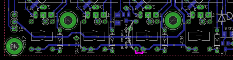
The C3 cathode row is missing a PCB trace. Join the two legs of SW19 as shown in pink, preferably on the bottom of the PCB. The LED cathode leg could simply be bent across to the switch pin.
Ghosting. As seems common with these kinds of matrices, there is some unwanted lighting of LEDs. This is most apparent when trying to light up the bottom row of MEC switch LEDs, as the resistive path to the Superflux LED is lower and thus glows unintentionally. This can be overcome somewhat by stacking BAT54 Schottky diodes on top of the BC818 transistors. Later revisions will have more elegant mounting.
Assembly
Take your time as some of these parts require some patience.
LEDs
High-brightness LEDs are often expensive or don't have viable mounting options. To get around this, we will use flat-top superflux/piranha RGB LEDs and bend the legs over to make a pseudo SMT part :). There are at least two different LED pinouts, so make sure you know how yours function.
Important is:
- Flat top (or maybe a filed-down dome)
- RGB LEDs with a common cathode
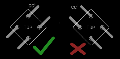
- With the LED standing on its legs, viewed straight on, rotated 45° and the cathode at the top, the cathode leg must bend to the right. You will see why!
- Get the board as flat as possible, rear side facing up. If the LEDs protrude through the PCB cutouts, they will prevent the switches from being soldered in later.
- Identify the LED cathode and place it in the 45° hole with the cathode aligned with the common cathode (CC) pin.
- Stating the obvious: the LED legs should be pointing up!
- Using a screwdriver or other tool, bend the LED legs down, first against the body then so the leg runs flat against the pad.
- You may wish to leave the cathode pins unbent for now, as these should either be soldered carefully so the switch can still go in or simply left until it is time to install the switches.
- Probably bend all of the LEDs first before soldering any.
- Solder at least the three anode pins, again making sure that no LED protrudes through to the front side of the board and that the cathodes are in the correct positions.
Transistors
- Transistors T9-16 (BC808 PNP) are soldered on the top side of the board. When the whole thing is assembled, these will not be accessible, so it's important to do them right.
- Don't mix them up with the BC818 NPN transistors!
- Transistors mount square on. Don't try to mount at a funny angle!
Bottom-side components
- SMT resistors
- Now you can use the BC818s! Note they are distributed across the board.
- Resistors R18-25 adjacent to the transistors can be omitted
- ICs1-5. Note that the 595s point in a different direction to the 165s!
- Diodes, apart from the one next to C6, which is omitted. Ensure the legs won't interfere with the Matias switches.
- THT resistors R1-16
- take special care with R2, R3, R13 and R14 that the legs are as short as possible (even top-solder them). The encoder legs from the PCB stacked above will come down here.
- resistor networks. It's very important to have the pin 1 dot aligned with the silkscreen marking.
RJs
The LEDs are available in RGB, but the official MIDIbox SEQ software only supports two of these colours. (if wanted, you could attach 0.1“ headers to the PCB and drive the LEDs with custom hardware.) So we need to select what LEDs are in the matrix using the resistor jumpers (RJ). Find RJ1-8 spanning across the middle of the board. Pins A(1-8) and B(1-8) represent the 8 anode busses and pins 1, 2 and 3 represent the pins of the LEDs in the row.
- For the ELV-sourced LEDs, pin 1 as marked on the PCB is the red LED and pin 2 is the green one. You can mix the LED colours, e.g. if you wanted to show step 1 (and 9) as a different colour.
- For the Mouser-sourced LEDs, the pinout is different. You can always check the colours of LEDs by using the diode tester of your multimeter.
- Say we want red and green LEDs throughout. Simply solder RJ1-8 with 47R from A to 1 and B to 2 for each instance. RJ9 should match RJ1. For blue and green, solder A to 2 and B to 3 (depending on the LED used).
- Pinheader J4 is a vestigial connector and could be used for two extra LED functions.
RJ9 connects to the Beat LED and so 100-220R resistors should be used here.
SJs
- SJs are similar. As the current is quite high to drive the RGB LEDs, it's wise to use a 100-220R resistor to provide suitable current to the MEC LEDs.
- The position should match 1, 2 or 3 (two arbitrary positions) according to how the RJ of the same column is connected.
- Note that the forward voltage of the MEC switch LED should be the same as the position chosen on the RGB LED.
- For instance, if RJ was set to “3” (blue LED) and a red LED was used in a MEC switch, then the current path may illuminate the red one over the blue.
Headers
Continue on with the header pins. J5 should be connected to the Beat LED PCB; this needs some more thought. Header J14 can be used as a +5V supply. 1*10 Headers J1-3 can be installed, but best in conjunction with the ENC-PLATE PCB to ensure correct alignment.
Here is a good point to test out the BLM function. Some MB_NG app? With the Plate PCB to test out the DIN side?
Switches
Notice that the switches have not yet been soldered in. It should be alright to put in the MEC switches, as long as the LEDs have been inserted first! Like the Jog module, the switches must be installed with the LEDs polarised correctly. The clearance with the Plate PCB is tight, so keep them straight.
Note the LED polarisation:
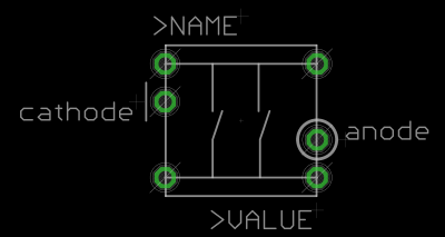
Very important: the Matias switches must go in through the completed Plate PCB! If they are put in before the Plate PCB, the Plate PCB won't fit and there will be no way to mount the encoders!
Once the Matias switches are in, this should basically be the final step of le MEC.
License
Currently the design is © 2017 antilog devices with all rights reserved; all documentation is CC BY-NC-SA 3.0.