SEQv4+ Jog module
A BLM using 18 illuminated MEC switches placed around an encoder (datawheel). Two spare DIN pins can accommodate a footswitch and a modular gate.
Schematic
The circuit is a BLM, but only four DIN columns are used. The other four DIN pins scan an encoder and two inputs intended as footswitch/gate. Standard SRIO in on J89 and chained out on J89A.
The BLM is as follows:
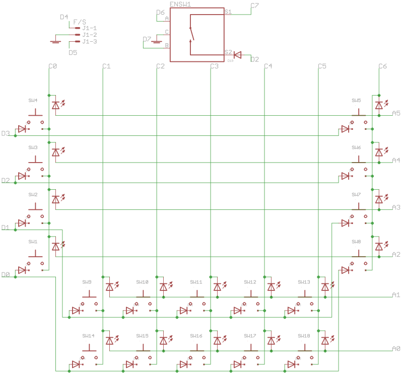
Note the encoder connected to pins D7 and D6, and header J1 connected directly to D5 and D4. All of the cathode rows are used, even C7 just for the encoder push switch.
Only six DOUT anode columns are used. These are current limited by resistors R1-6.
BOM v1.0
Please find the current BOM on http://midiphy.com. The table below is depreciated and will not be updated.
| Type | Qty | Value | Package | Parts | Mouser | Reichelt | Conrad | Other | Notes |
|---|---|---|---|---|---|---|---|---|---|
| Resistors | |||||||||
| 6 | 100-220R 5% | THT | R1-6 | ||||||
| Resistor network | |||||||||
| 1 | 10k | SOM16 | RN1 | 4816P-T02-103LF | |||||
| Capacitors | |||||||||
| 3 | 100n | 1206 | C1-3 | ||||||
| Diodes | |||||||||
| 19 | 1N4148 | THT | |||||||
| LEDs | |||||||||
| 18 | various | 3mm | insert into switches | ||||||
| ICs | |||||||||
| 1 | 74HC165 | SOIC16 | IC2 | 595-SN74HC165DR | |||||
| 2 | 74HC595 | SOIC16 | IC1, IC3 | ||||||
| Encoder | |||||||||
| 1 | STEC12 | STEC12E08 | |||||||
| Switches | |||||||||
| 18 | MEC/APEM | 3FTH9 | SW1-18 | 642-3FTH9 | TASTER 3FTH9 | 705276 - 62 | |||
| Headers | |||||||||
| 1 | 1*3 | male | |||||||
| 2 | 2*5 | male | |||||||
| Hardware | |||||||||
| 6 | M3 spacer | TBD | |||||||
| 1 | datawheel | DK-38? | |||||||
| 0 | switchcaps | 22.5mm | 642-1S11-22.5 | 1S11-22.5 | original parts, when using taller jogwheel. See next line | ||||
| 18 | switchcaps | 19mm | 642-1S11-19.0 | 1S11-19.0 | waiting on case, but probably the 19mm caps will be used here too | ||||
Versions
v1.0: first release.
Assembly
Start with the SMT parts (caps, ICs and RN), then the resistors and diodes with correct polarity. Headers, switches (read below first!), encoder, caps and knobs.
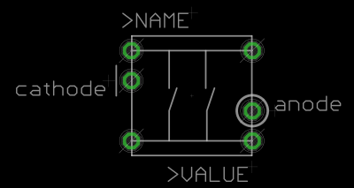
Important: insert the LEDs into the switches before soldering them! It's quite hard to bend the legs once the switches are in place. The LED legs should not interfere with the switch action; i.e. the button should be pressed and released without getting caught on the legs.
Ensure that when the switch is soldered in, the LED is correctly polarised. Round part (anode) of the LED to the circled pin; flat part (cathode) to the line:
License
Currently the design is © 2017 antilog devices with all rights reserved; all documentation is CC BY-NC-SA 3.0.