Table of Contents
AC Sensorizer v0.4
Description
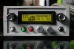
AC Sensorizer sensorizes up to 8 sensors and interpolates its AIN-readings. The main target of this application are sensory devices delivering not exactly 0 - 5 V, like pressure-, distance-, resistor-based sensors or softPots.
These two videos show the ACSensorizer 0.2 which is using an outdated HUI, but nevertheless the concept of the Sensorizer is demonstrated quite well:
The ACSensorizer has been developed by Audiocommander ( http://www.audiocommander.de )
© 2007 Michael Markert
This software is released under a GNU License. You are not allowed to use this software or parts of it in closed-source projects! Please notice that due to the licenses for MBHP and MIOS you may only use the Hard- and Software for private purposes. Non-commercial use only!
Please contribute and name the author(s)!
Features
- supports up to 8 sensors
- enable/disable single AINs
- assignable CH and Controller-Number or Note_On generation (!)
- harmonizer with 20 scales (minor, major, blues, spanish…) ⇒ harmonizes generated or received (by MIDI!) note-signals
- syncronizer: master/slave mode (autodetect clock input switches to slave) and selectable BPM
- quantized events: 1/2/3/4/6/8/12/16/24/32/48, selectable per sensor
- adjustable input range by sense-min and sense-max (10bit values, ignore if not matched)
- adjustable output range with “scale from and scale to”
- sense-factor: used for signal interpolation… uses fast bitshifting or complex division depending on value
- AUTO-sense feature: auto-calibration of sensor, detect MIN/MAX and automatically adapts sense-factor!
- invert signal
- pedal modes:
- filter ⇒ only forward if pedal down;
- panic ⇒ send panic on release pedal;
- combinations of all pedal mode options are possible
- detect release: send 0-value if signal drops below sense-min
- slowdown: slows down the signal and increases the gaps between generated values
- bankstick support: 1 connected bankstick provides 2 banks with 127 patches each (24LC256)
- midi configurable: full configuration possible with NRPN-messages
- NRPN-MSB CC99 for sensorSelect / sysEx mode
- NRPN-LSB CC98 for controlType
- DataEntry MSB CC6 and LSB CC38 for controlValue
- Mac OS X Onscreen Config Program and MiniAudicle Setup Script examples included!
- LCD (2×16) with clearly structured menu for sensor-select, prg-select, sensor-config & -settings
- redesigned HUI Input to enable better control with less hardware requirements
- (optional) DOUT module supported (Sensors can be illuminated)
- ACSim Console Debugger: code integrated and ready to use configured for XCode
- select “ACSim” as target and test the application via command-line
- inspect variables with a (graphical) debugger (GDB support within XCode)
- visit midibox.org - there's a tutorial how to use CodeBlocks
Required hardware
MBHP Modules:
- one MBHP_CORE module
- one MBHP_LCD module (2×16)
- one MBHP_DIN module for
- 4 Encoders (no push-button functionality needed!)
- 1 PEDAL button
- 1 PANIC button
- 1 STORE and 1 WRITE button
- 1 pedal-input (jack at the backside)
- one MBHP_DOUT module for illuminated sensors (optional)
Sensors:
- up to 8 sensors connected to unmuxed AIN (J5 of MBHP_CORE).
- more informations on sensors can be found here: sensors

It is possible to use the sensorizer with only one Core Module. For these purposes a MAC OS X program is included to simulate encoders and buttons. You can easily test the application with one core module!
Application Software
- http://www.audiocommander.de/downloads/midibox/ACSensorizer_046.zip, 324 kB, released on 2007-11-10
- still BETA, but quite stable
- Please report bugs or errors here: ACSensorizer Forum Thread – audiocommander
Version History
- v0.1.0 2005-12: First testing versions, no code reused
- v0.1.1 2006-01: AIN-config, gate, expander, main functionalities
- v0.1.2 2006-01: Improved expander, inverter, smaller filesize
- v0.1.3 2006-04: Cleanup, code-splitting, rewrite (many fixes!)
- v0.1.4 2006-04: Improved inverter, expander, signal routing
- v0.1.5 2006-04: Added Bankstick Accessors (16byte / sensor)
- v0.1.6 2006-06: Rewrote Bankstick related functions, optimized vars
- v0.2.0 2006-07: Rewritten from scratch, optimized var-access & efficiency, added ENC and LCD menu (2×16/4×20 optimized) support (in main.c)
- v0.2.1 2006-08: Rewrote Bankstick Support (in main.c), 2×64 bytes per patch
- v0.2.2 2006-08: improved algorithms, added sensemode (efficient or exact), added pedalMode, releaseDetect config and PRG-CH, initial release
- v0.2.3 2006-09: minor bugfixing, removed MidiTrough and used MIOS_Merger, two example miniAudicle/Chuck NRPN scripts are now included
- v0.2.4 2006-09: fixed severe bank select bug (B,D,F,H,J,L were not accessible)
- v0.3.0 2006-09: rewritten main class, better HUI concept, re-organized Encoder Input, autoload patch #0 (in case of reset), added pedal to start/stop AutoSense Mode, corrected sensor-level-view for sensors 4..8
- v0.3.1 2006-10: added Clock-Sync support / Continue-Hack for m4, added clock-forwarding, even if mios_merger disabled
- v0.3.2 2006-11: fixed PRG-CH bug
- v0.4.0 2006-12: added harmonizer support, patches maintain full backward-compatibility to v0.2.1 versions
- v0.4.1 2006-12: added HUI Midi Remote Control (Simulate Encoder Movements)
- v0.4.2 2007-04: syncronizer support, unified ACMidiProtocol
- v0.4.3 2007-04: added bpm control (48..255 bpm), patches save harmonies & sync, fixed broken master/slave detection, CCs Sustain, Sustenuto & Soft Pedal (Damper) may also control the Pedal. Patch Names are now supported (7 chars max). Last active patch is stored in EEPROM and loaded on startup
- v0.4.4 2007-07: ENC_Speed optimized for Voti.nl encoders, autosense bugfix, Documentation cleanup & updates, release
- v0.4.5 2007-08: sync start signal now recognized (SLAVE & MASTER), continue is sent each bar (MASTER), start on patch load (MASTER), harmonizer now working correctly with base notes, release
- v0.4.6 2007-11: fixed MST/SLV autodetection bug, now behaves correctly; PANIC also sends STOP in MASTER mode (LOAD sends START); Global Channel now defaults to CH16, messages are sent/received on all channels except for PRG_CH (Global CH only) release
- v0.4.7 2007-11: Added DOUT support for external Sensors with LEDs; now recognizes QUANTIZE_SET as well (ACMidiProtocol), fixed QUANTIZE_BPM bug
- v0.5.0 2009: currently in work, future release will contain source compatibility maintenance for new toolchain, mac os x remote control & patch viewer… stay tuned!
Compiling Notes
The application can be recompiled with a variety of strictly separated #define- options. For example setting SENSORIZER_INTERFACE_HUI to 0 compiles the application without hardware input controls and therefore reduces the file- and application space. Compiling without HUI, BANKSTICK, NRPN-Config and LCD generates code with approx. 3 or 4 pages; compiling with all options will result in an application file of 19 pages.
HUI-Controllable Parameters
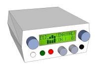
The Sensorizer provides:
- one 2×16 LCD
- four Encoders
- four Buttons
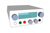
| Front Side | ||
|---|---|---|
| Top | Left Encoder | current sensor selector (1..8) |
| Right Encoder | Menu Selection Wheel | |
| Bottom | White Button | PANIC |
| Green Button | LOAD PATCH | |
| Red Button | STORE PATCH | |
| Left Encoder | Value setter for selected menu item / parameter 1 | |
| Right Encoder | Value setter for selected menu item / parameter 2 | |
| Black Button | PEDAL (2nd pedal connector at the rear) |
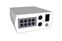
| Back Side | |||
|---|---|---|---|
| Left | 8 6-pin Mini-DIN connectors | For up to 8 Sensors | Connector Type can be changed! |
| Middle | 5-pin DIN connectors | Midi-In and Midi-Out | |
| Middle Center | 6.5mm Jack | External Foot-Pedal | A pedal is highly recommended! |
| Right Top | Switch | ON/OFF Switch | |
| Right Bottom | DC Connector | +9V DC Power Supply | Connector Type can be changed! |
Manual: Interface
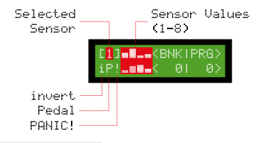
The Interface is clearly structured; the encoders control the values on the screen next to them. A minimum set of additional buttons allow loading and saving of patches, sending PANIC! and an alternative pedal knob (it is recommended to add a second pedal on the backside. MIDI pedals (like Sustenuto or Pedal are of course also supported.
Manual: LCD-Menu
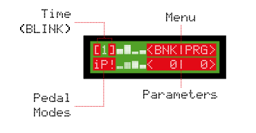
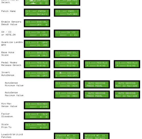
The following picture contains an overview of the onscreen LCD-menu structure. Click to view larger version:
MIDI Implementation Charts
See below which MIDI messages are recognized and sent by ACSensorizer:
| Message Type | Received | Sent | Notes |
|---|---|---|---|
| NOTE ON | x | x | Harmonized |
| NOTE OFF | x | x | Harmonized |
| POLY AFTERTOUCH | - | - | |
| CC | x | x | See CC Message Table |
| PROGRAM CHANGE | G | G | Global Channel only |
| CHANNEL AFTERTOUCH | - | - | |
| PITCH WHEEL | - | - |
Table A: MIDI Messages Implementation Chart
| CC | Name | Received | Sent | Notes |
|---|---|---|---|---|
| 0-127 | see below | x | ||
| 0 | Bank Select | G | G | Global Channel only! |
| 6 | Data MSB | x | x | See NRPN Table D |
| 38 | Data LSB | x | x | See NRPN Table D |
| 64 | Pedal | x | x | Pedal |
| 66 | Sostenuto | x | x | Pedal |
| 67 | SoftPedal | x | x | Pedal |
| 80 | Harmony Base | x | x | Harmony (ACMidiProtocol) |
| 81 | Harmony Scale | x | x | 0..20 |
| 82 | Harmony Base Listen | x | x | <> 63 |
| 83 | Harmony Scale Previous | x | x | > 63 |
| 84 | Harmony Scale Next | x | x | > 63 |
| 85 | Harmony Random | x | x | > 63 |
| 87 | Quantize BPM | x | x | BPM = [0..127] + 60 |
| 98 | NRPN LSB | x | x | See NRPN Table C |
| 99 | NRPN MSB | x | x | See NRPN Table C |
Table B: Controller Change Implementation Chart
x YES
– NO
G Global Channel only
The channel numbers that are counted from 1 to 16 appear as 0 to 15 in code!
For more information on ACMidiProtocol supporting interchangeable notifications on BPM, Harmony and Scale changes, see ACMidiProtocol.h!
NRPN Controls
All Sensorizer parameters can be controlled and set by sending NRPN messages by MIDI:
- Send NRPN MSB (Controller# 99) to select control type
- Send NRPN LSB (Controller# 98) to set the control parameter
- Send NRPN Data MSB (Controller# 6) and NRPN Data LSB (Controller# 38) to set the parameter value
| NRPN MSB | |||
|---|---|---|---|
| CC | Value | Control Type | Note |
| CC99, 0x63 | 0x00..0x07 | Sensor 0..7 | LBS 98, See Table B |
| CC99, 0x63 | 0x60 | Sensor Wheel | LSB 98, 0..8 |
| CC99, 0x63 | 0x61 | Menu Wheel | LSB 98, 0..10 |
| CC99, 0x63 | 0x62 | Param Wheel A | LSB 98, 0..127 |
| CC99, 0x63 | 0x63 | Param Wheel B | LSB 98, 0..127 |
Table C: Control Types
| NRPN LSB | DATA ENTRY MSB/LSB | ||||
|---|---|---|---|---|---|
| CC | Value | Control Parameter | CC | Value | Description |
| CC98, 0x62 | 0x00 | enabled | CC38, 0x26 | 0/1 | ON/OFF |
| CC98, 0x62 | 0x01 | pedalMode | CC38, 0x26 | 0..7 | FILTER/HOLD/PANIC/KOMBI |
| CC98, 0x62 | 0x02 | autoSense | CC38, 0x26 | 0..2 | AUTOSENSE_OFF/_MIN/_MAX |
| CC98, 0x62 | 0x03 | invert | CC38, 0x26 | 0/1 | 0..127 or 127..0 |
| CC98, 0x62 | 0x04 | releaseDetect | CC38, 0x26 | 0/1 | send 0 on release |
| CC98, 0x62 | 0x10 | slowdown | CC38, 0x26 | 0..127 | drop AIN notifications |
| CC98, 0x62 | 0x11 | sense_min | CC38, 0x26 & CC6, 0x6 | 0..1023 | drop below and set sense minimum |
| CC98, 0x62 | 0x12 | sense_max | CC38, 0x26 & CC6, 0x6 | 0..1023 | drop above and set sense maximum |
| CC98, 0x62 | 0x13 | sense_factor | CC38, 0x26 | 0..64 | f=(range/127) |
| CC98, 0x62 | 0x21 | scale_from | CC38, 0x26 | 0..127 | restrict and rescale output |
| CC98, 0x62 | 0x22 | scale_to | CC38, 0x26 | 0..127 | restrict and rescale output |
| CC98, 0x62 | 0x70 | CH | CC38, 0x26 | 0..15 | MIDI Channel of sensor |
| CC98, 0x62 | 0x71 | CC | CC38, 0x26 | 0..127 | MIDI Controller Change Number of sensor |
Table D: Control Parameters
Examples:
Turning the Menu Wheel (virtually):
- Send NRPN MSB (Controller# 99) with value 0x61 to select control type
- Send NRPN LSB (Controller# 98) with value 0 to 10 to set the control parameter
- No NRPN Data MSB (Controller# 6) and NRPN Data LSB (Controller# 38) required
Setting the CC to send for (already selected) sensor 1:
- Send NRPN MSB (Controller# 99) with value 0x00 to select the setting for sensor 1 (or 0x01 for sensor 2)
- Send NRPN LSB (Controller# 98) with value 0x71 to set the control parameter “CC” for the selected sensor
- Send NRPN Data MSB (Controller# 6) with a value from 0 to 127 to set the CC Number. NRPN Data LSB (Controller# 38) is not required (only for values greater than 127)
BANKSTICK Patch Description
ACSensorizer supports writing and reading to 24LC256-type banksticks.
Each patch consists of 2 pages à 64 bytes ⇒ 128 bytes
2 banks with 128 patches each are available per 1 connected bankstick (24LC256)
Choose the appropriate bank by sending a Coarse-Adjust Bankselect (CC#0).
In HUI-Mode, switching a bank on the device also sends the current Bank/PRG.
Memory-map of one patch:
| Data | Size in Bytes = Sum | Page | Address |
|---|---|---|---|
| Version | 1 = 1 | 1 @ 0x00 | 0 @ 0x00 |
| PatchName | 8 = 9 | 1 | 1 @ 0x01 |
| <reserved> | 7 = 16 | 1 | 10 @ 0x0A |
| BPM | 1 = 17 | 1 | 16 @ 0x10 |
| <reserved> | 5 = 22 | 1 | 17 @ 0x11 |
| harmony_base | 1 = 23 | 1 | 22 @ 0x16 |
| harmony_scale | 1 = 24 | 1 | 23 @ 0x17 |
| sensor[8] | 8 = 32 | 1 | 24 @ 0x18 |
| CH[8] | 8 = 40 | 1 | 32 @ 0x20 |
| CC[8] | 8 = 48 | 1 | 40 @ 0x28 |
| sync_1[8] | 8 = 56 | 1 | 48 @ 0x30 |
| <reserved> | 8 = 64 | 1 | 56 @ 0x38 |
| slowdown[8] | 8 = 8 | 2 @ 0x40 | 0 @ 0x00 |
| sense_factor[8] | 8 = 16 | 2 | 8 |
| sens_min[8].MSB | 8 = 24 | 2 | 16 @ 0x10 |
| sens_min[8].LSB | 8 = 32 | 2 | 24 |
| sens_max[8].MSB | 8 = 40 | 2 | 32 @ 0x20 |
| sens_max[8].LSB | 8 = 48 | 2 | 40 |
| scale_from[8] | 8 = 56 | 2 | 48 @ 0x30 |
| scale_to[8] | 8 = 64 | 2 | 56 |
Table E: Bankstick Patch Content
Patch addresses are: (patch * 0x80)
or PIC-optimized: (unsigned int)patch « 7
Example hex-output of patch#0 for Sensorizer > 0.4.0:
**MIOS_BANKSTICK_WritePage at 0x0
 0:     04 44 65 66 61 75 6c 74 00 ff 00 00 00 00 00 00  .Default........
16:     78 00 00 00 00 00 00 14 81 81 81 81 00 00 00 00  x...............
32:     00 00 00 00 00 00 00 00 14 15 16 17 18 19 1a 1b  ................
48:     08 08 08 08 08 08 08 08 00 00 00 00 00 00 00 00  ................
**MIOS_BANKSTICK_WritePage at 0x40
 0:     02 02 02 02 02 02 02 02 04 04 04 04 04 04 04 04  ................
16:     00 00 00 00 00 00 00 00 40 40 40 40 40 40 40 40  ........@@@@@@@@
32:     03 03 03 03 03 03 03 03 70 70 70 70 70 70 70 70  ........pppppppp
48:     00 00 00 00 00 00 00 00 7f 7f 7f 7f 7f 7f 7f 7f  ................
A reference to the last active patch (bank/prg) is stored in EEPROM to enable reloading on next startup. each time a patch is successfully loaded or stored the reference is automatically saved.
The available EEPROM adress range is from 0xF00000 to 0xF000FF (256 bytes):
| EEPROM Address | Data | Size (bytes) |
|---|---|---|
| 0x00 - 0x01 | last bank | 1 byte |
| 0x01 - 0x02 | last patch | 1 byte |
| 0x02 - 0xFF | <reserved> | 254 bytes |
Table F: EEPROM Content
Step-By-Step Building Instructions
1. MBHP Core
Follow the instructions at http://www.ucapps.de/mbhp_core.html. Don't forget to add MIDI-Cables and a 9V/800mA Power Supply!
2. MBHP LCD
Follow the instructions for a 2×16 LCD at http://www.ucapps.de/mbhp_lcd.html
3. MBHP DIN
Follow the instructions at http://www.ucapps.de/mbhp_din.html
4. MBHP DOUT
(optional) If you have lights on your Sensors, you can add a DOUT module: http://www.ucapps.de/mbhp_dout.html
5. MBHP Bankstick
Follow the instructions at http://www.ucapps.de/mbhp_bankstick.html. I'm using the Bankstick PCB supporting up to 8 Banksticks; maybe one Bankstick is sufficient for you (1 BS provides two banks with 127 patches each = 256 patches per Bankstick).
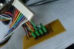
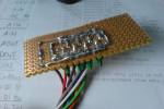
6. AIN “Breakout Board”
I use to solder extra 3-pin connectors on a seperate PCB. These pins allow quick grounding with a jumper or to switch the sensors easily to check for hardware errors. And it's a lot smarter to assemble the case without having to desolder all connections ;)
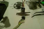
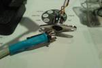
7. AIN Cables
I'm using 6-pin Mini-DIN connectors. In theory, a three-pin connection would be sufficient, but with a 6-pin cable, I can use 2 pins for an external voltage supply or additional DIN/DOUT lines.
8. Encoders and Buttons
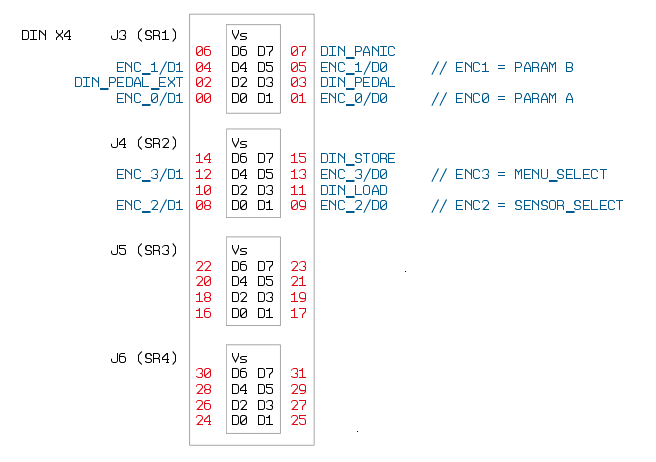
9. DIN Connections
Connect the Encoders and Buttons as shown on the following table. The DIN module has to be connected to J9 of core module (see din_module for connection diagram with SmashTV Core modules.
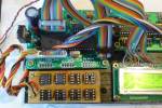
The following image is the upper view of a DIN-Board from Smash TV, check this PDF if you are using the "standard" design from ucapps (just note the name of the pins - D0,D1, D2, etc…):
10. DOUT Connection
(optional) Connect the Dout Pin #1 to a LED that sits in Sensor #1 (#2 to #2, #3 to #3 and so on…).
11. Upload MIOS
I'm running it with MIOS8 (PIC) 1.9e, but it should work with any newer 8-bit version. An update to the new app-structure is planned. See Downloads… and MIOS8 Upload for Newbies
12. Upload ACSensorizer
Upload “ACSensorizer.hex” /-OR-/ “ACSensorizer.syx” (depending on the method you are using… ⇒ see “Uploading an Application” at MIOS8 Upload for Newbies)
13. Sensor Calibration
- Connect your sensors
- Disable all sensors but the first one (Menu: ENA ⇒ OFF)
- “from” should be “0” and “to” should be “127”
- Try Autocalibration first:
- Menu: AUT → MIN ⇒ Trigger the minimum value of the sensor, then press the pedal. Release the pedal once you have the right minimum value.
- Menu: AUT → MAX ⇒ Trigger the maximum value of the sensor, then press the pedal. Release the pedal once you have the right maximum value.
- Menu: AUT → OFF
- Repeat these steps for the remaining sensors.
- If the automatic calculations aren't satisfying, which may be the case if you're using sensors with a “jumpy” behavior like IR Distance sensors, you can set the sensing MIN/MAX values by hand. Do not mix up with the Scale from/to values these are just to interpolate the final signal:
- Measure the electrical min/max values or take them from the datasheet ( Example: 0.2V min to 2.5V max )
- Calculate the 10bit minimum (Factor 1024 / 5V = 204.8) : 0.2Vmin * 204.8 = 40.96 ⇒ as 8bit number: 40.96 / 4 = 10.24 ⇒ Enter 15 as MIN. Note that the value is just shown as 8bit value, internally it's a 10bit value. That's why you need 4 Encoder detends to go from 128 to 129…
- Calculate the 10bit maximum (Factor 204.8) : 2.5Vmax * 204.8 = 512 ⇒ as 8bit number: 512 / 4 = 128 ⇒ Enter 128 as MAX
- Now set the sense-factor, Menu: F. The sensorized value gets divided by this factor to get the 7bit value. Normally this would be 8 (1024 / 127 = 8) ⇒ in our example: 512 max (10bit) / 127 = 4 ⇒ Enter 4 as F
- Proceed with the remaining sensors and Save your patch.
Done!
This site is about to change while the Sensorizer is beeing developed further!
have fun! – audiocommander


