"Apparat 20" construction blog
(“Apparat” is an old-fashioned german word for a telephone or also for the extension number of a phone.)
As I just started with my next MidiBox project, I thought this time I´ll have to contribute a build blog. So here we go:
Concept
The idea is to build a synthesizer together with a vocoder into an old telephone. This brings up a few considerations:
Telephone
I really wanted a “Plug'n'Go” thing for stage use, so everything must fit into the phone. This means (of course) the phone needs to offer some space inside and has to look cool. I chose this phone - it's an 80ies phone built by SEL from the “design” line of the Deutsche Telekom. It emerged from a phone for disabled people, hence the really BIG dial buttons.
Vocoder
The vocoder has to be as small as possible. Mostly, vocoding is found in (at least) 9.5“ FX units. Standalone vocoders (like the MAM VF11 or DIY versions) are normally analogue and even bigger units. Then I found the Alesis Metavox - it´s the smallest (14 x 8 cm) and also cheapest vocoder existing (got it for 30 EUR new). Most of its functions are not really useful for music, all around the internal oscillator/LFO is more like a DJ toy. But the sound quality in external mode is quite good.
Synthesizer
The carrier signal has to be polyphonic and should be quite brilliant to achieve good vocoder results. At first, I thought about using a MBSID but quickly rejected this idea. It's only polyphonic with (mostly boring) single oscillator sounds, and the higher frequencies are not really present. Even more, The vocoder would have to be used with the normal filter switched off, so a great part of the SID character would be gone anyway. So the choice is the MB FM.
"User Interface"/Features
My central objective is that the finished Apparat 20 should just look as much as possible like an ordinary phone. So there won´t be a display or any additional CS elements for the MBFM. Up to 20 patches will be selected via the normal dial keys (1..0, and you can select two “banks” with # and *). I can imagine some of you saying “But you can´t edit anything and wouldn´t it be cool to have this or that parameter accessible in live performance?”. Of course it would, but I'm building a big MBFM for home use anyway, and there's always JSynthLib…
The vocoder has only one single parameter to modify when external mode is selected (Siblance, i.e. how much high frequency of the original signal will bleed thru, i.e. consonants). The corresponding pot will be mounted hidden beneath the handset. Picking up the handset will switch off the vocoder bypass and it will get an electret capsule and a simple mic pre.
Build Blog
the phone
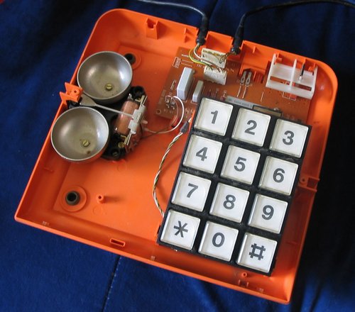
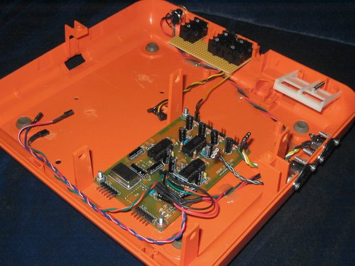
This is what the phone looks like inside - you can see there's quite some room in there.
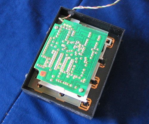
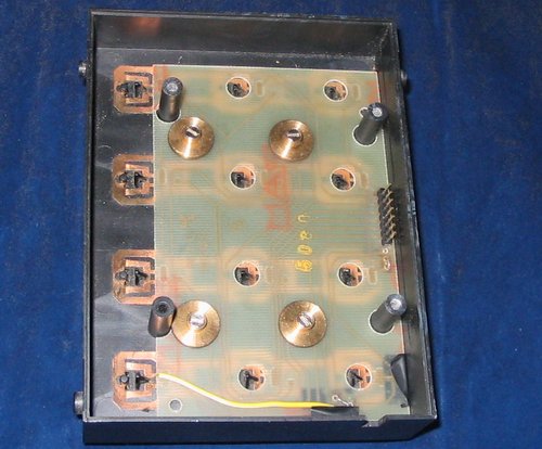
After throwing everything out, I examined the keyboard to find out how to use it.
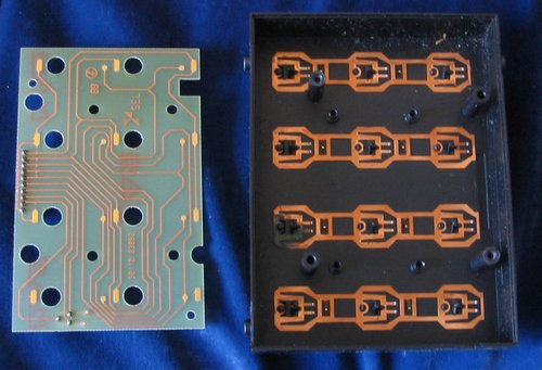
Under the control board there is a simple 4×3 button matrix (without diodes - but that's no problem, it won't be necessary to press more than one button at the same time).
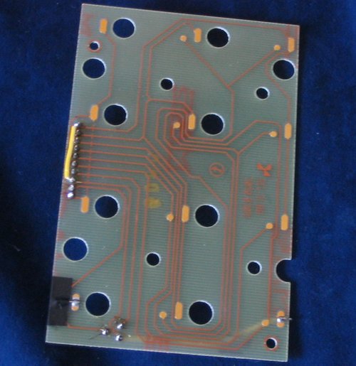
Because the contacts for the # and * buttons were not connected, I had to solder a few thin wires and I rewired the connector:
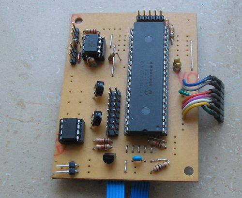
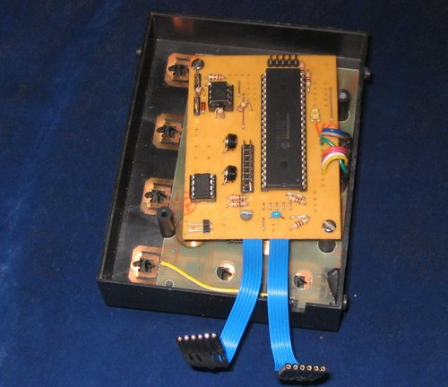
There's some space under the keypad, so I decided to mount the Core directly onto the backside of the keypad - the OPL3 module will still fit beneath it.
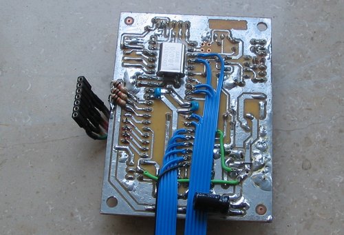
I built a simple Core module with most of the connectors and the PSU section left out - the phone will be powered from the nice +5V, +/-12V PSU I bought cheaply from Pollin last year, so there's no need for rectifier, regulator etc.. That way there was enough unused space on the PCB that I could cut a few tracks and add the BankStick directly to the core PCB. The LCD and D_IN connectors are mounted only for debugging.
The keypad matrix is connected to J5. There are 10k PullDown resistors where the three columns are connected. The OPL3 board wires were a bit tricky - the pin order is swapped because of the board being mounted heads-down.
Software changes for the matrix keyboard
So now I had a keyboard with integrated core - how to scan the key matrix? There are the sm_examples from Thorsten, but the FM has hardly any RAM left and it's also preferable not to use too much processing power. Debouncing is not necessary, because every button press is a single key action and it doesn't hurt if the same Program Change is executed a few times. So I chose to do my own simple matrix scan.
There are a few preparations necessary: First, I defined the two variables MATRIX_BUTTON and MATRIX_LAYER. Then at the end of USER_Init (main.asm) I inserted this:
    ;; ------- prepare scan matrix --------------------------------------

    ;; disable the ADC which allocates the analog pins
    movlw	0x07
    movwf	ADCON1

    ;; Initialize J5 (PORTA 0..3,5 output, PORTE 0..2 input)
    bcf TRISA, 0	; Pin RA.0 = output
    bcf TRISA, 1	; Pin RA.1 = output
    bcf TRISA, 2	; Pin RA.2 = output
    bcf TRISA, 3	; Pin RA.3 = output
    bcf TRISA, 5	; Pin RA.5 = output
    bsf TRISE, 0	; Pin RE.0 = input
    bsf TRISE, 1	; Pin RE.1 = input
    bsf TRISE, 2	; Pin RE.2 = input

    ;; set initial state
    bcf LATA, 0
    bcf LATA, 1
    bcf LATA, 2
    bcf LATA, 3
    movlw 0x00
    movwf MATRIX_BUTTON
    movwf MATRIX_LAYER
;; --------------- end modification -----------------------------------------

#if CS_ENABLED
	;; reset the control surface
	goto	CS_MENU_Reset
#else
	return
#endif
The scanning is done in cs_menu_timer.inc. The following code is inserted at the beginning of the CS_MENU_TIMER function:
CS_MENU_TIMER

    ;; --------------- scan button matrix ---------------------------------------
    ;; rows on PORTE (with 10k PullDown resistors)
    ;; cols on PORTA (0..3)

    movlw 0x00

    bsf LATA, 3
    IFSET PORTE, 0, movlw 0x01
    IFSET PORTE, 1, movlw 0x02
    IFSET PORTE, 2, movlw 0x03
    bcf LATA, 3

    bsf LATA, 2
    IFSET PORTE, 0, movlw 0x04
    IFSET PORTE, 1, movlw 0x05
    IFSET PORTE, 2, movlw 0x06
    bcf LATA, 2

    bsf LATA, 1
    IFSET PORTE, 0, movlw 0x07
    IFSET PORTE, 1, movlw 0x08
    IFSET PORTE, 2, movlw 0x09
    bcf LATA, 1

    bsf LATA, 0
    IFSET PORTE, 0, movlw 0x11
    IFSET PORTE, 1, movlw 0x0A
    IFSET PORTE, 2, movlw 0x10
    bcf LATA, 0

    movwf MATRIX_BUTTON

;; --------------- end modification -----------------------------------------

  decfsz	CS_MENU_TIMER_CTR, F; since this routine is called every 1 ms, but the cursor
;; ...
Here MATRIX_BUTTON is set to a value greater 0 while a key is pressed. The result is then processed at the end of each USER_TICK in the main.asm:
;; --------------- Program Change on key press ------------------------------
    movlw 0x00					;; Button pressed?
    cpfsgt MATRIX_BUTTON
    return

    movlw 0x0f					;; Yes -> * or # ?
    cpfsgt MATRIX_BUTTON
    goto PATCH_SEL

    movlw 0x10					;; Yes -> select layer (1..10/11..20)
    cpfsgt MATRIX_BUTTON
    goto PATCH_10

    movlw 0x00					;; 1..10
    movwf MATRIX_LAYER
	return

PATCH_10					;; 11..20
    movlw 0x0A
    movwf MATRIX_LAYER
    return

PATCH_SEL					;; Normal patch selection
    movf MATRIX_BUTTON, W
    addlw (-1)
    movwf MIOS_PARAMETER2

    movf MATRIX_LAYER, W			;; Add layer
    addwf MIOS_PARAMETER2

    movlw 0xC0				;; Program Change Ch 1
    movwf MIOS_PARAMETER1
    call MBFM_MIDI_NotifyReceivedEvent

;; --------------- end modification -----------------------------------------
	return
Finishing the MBFM part
There will be some more coding necessary for the vocoder (the MB has to toggle one vocoder button 4 times on startup to select external mode, and the telephone hook has to toggle the bypass “pedal” (on/off) for every change), but the key scanning already works. So let's finish the MBFM.
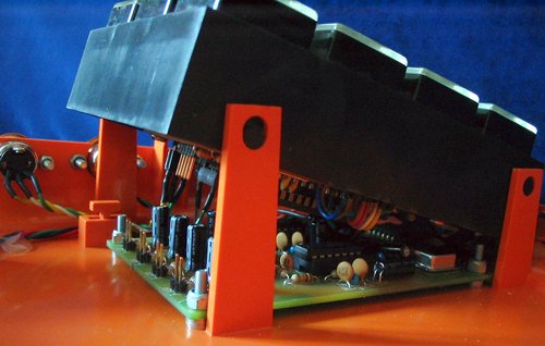
I milled away most of the mounting posts in the phone. All jacks and the OPL3 board were installed and the wiring for power and MIDI was done:
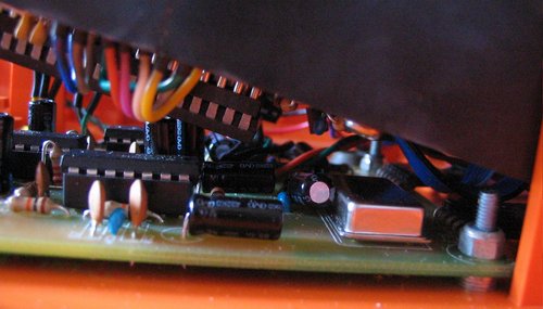
As the keypad descends towards the front, I laid all larger parts (mainly the electrolytics) flat on the boards. The clearance between the boards is quite narrow but sufficient not to fear any shorts etc.
Now, the phone contains a fully functional MBFM 
Modifying the Metavox
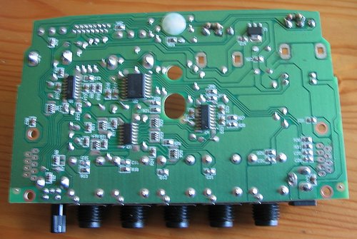
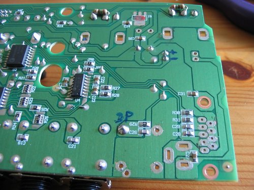
After disassembling the Metavox, I found out that there are two boards inside this tiny unit. The lower one has all the jacks and pots mounted and contains the PSU, the DSP and analog cirquits. The upper one has the buttons, LEDs and a small Philips MicroController. I will mount them above each other like in the original unit, but I want them to consume less space, so I started by desoldering all pots and jacks from the lower board. The three unused pots are replaced by two resistors to simulate a pot. The Siblance pot gets a connector.
The Metavox originally runs from a 9V AC wall wart, but the MBFM PSU delivers only 5V and +/-12V. So I followed the power traces - the 9V AC is divided in +9V and -9V DC via two diodes and there's a regulator bringing the +9V down to 5V DC. The +/- 9V are only used for the output opamp (standard TL series) that easily takes much higher voltages. So I desoldered the regulator (top of the following picture) and the diodes and put connectors for 5V, GND and +/-12V on the board. This way the output headroom will be just a bit higher.
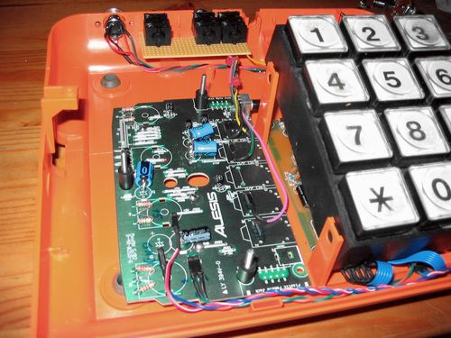
This is the lower board mounted and connected to the audio in/out jacks. Again, the capacitors are laid flat.
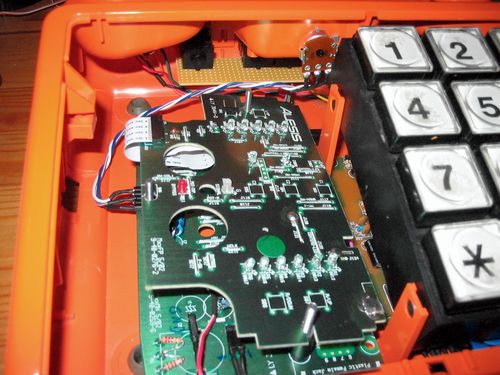
The second board connected. Behind the keypad there's the Siblance pot.
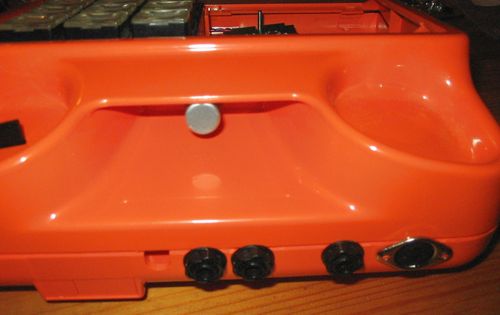
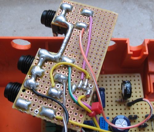
The pot and jacks seen from behind:
Chapter 2 (Sept 5, 2006)
the handset
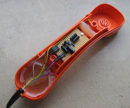
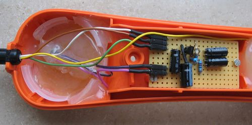
The vocoder needs a decent microphone with crisp high frequency response, so the original handset mic is to be replaced. I bought an electret capsule with good specs at Conrad. Then I searched the net for simple mic pre schematics. I came up with this page. It´s a really simple one transistor cirquit that works quite well. Simple was important because of size - the handset cable is not shielded and not twisted and therefore not suitable for mic-level transmission, so i built the pre amp right into the handset. The cable has 4 wires. Two are for power supply and one for the amplified signal, so it would even be possible to use the fourth wire to drive a handset speaker. I´m not sure if there would be problems with feedback though.
First I just put a piece of foam with a hole for the capsule into the handset, but the problem is that with such a small capsule in it, the handset makes a very hollow-sounding cave and is very sensitive to feedback. Glueing the capsule directly behind the grid is also no good because the mic gets very susceptible to pops and breath. So I took the plastic ring that held the original capsule. I laid it onto a baking paper and filled it with hot glue. After cooling down I got a plain surface that could be mounted easily with 2-3 mm distance to the grid. I drilled a hole into the glue and fixed the capsule with a little more of hot glue. Voila:
the bypass
The audio jacks are all wired so that you can insert other sources to the vocoder.
I found out that it´s a bit difficult to use the built-in vocoder bypass. The debouncing of the buttons is not very good on the alesis, so it happens quite often that you switch the bypass on and off again with one button press. When used “the normal way”, this is no big problem because you check the bypass LED anyway. But triggering this button from the core module it could happen that the pickup and the bypass state get “asynchronous”. Checking the LED state from the core is complicated, too. The LED is part of a matrix so there´s no simple way to measure on and off.
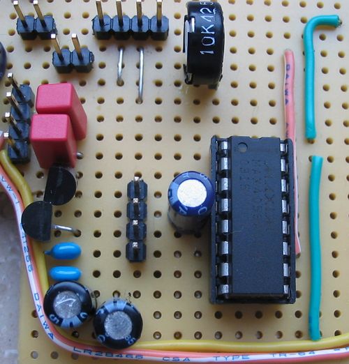
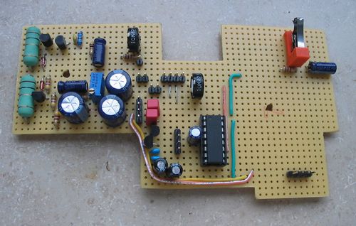
So I decided to do it in the analogue domain by using a 4053 chip. This is a 3x SPDT (dual throw) chip for analogue signals, similar to the 1×8 chip 4051 used in the MBHP AIN module. One problem with this chip is that it doesn´t work with +/-12 V. The standard 74hc4053 (e.g. from TI) takes only 5V but I happened to have left over a few max4053 ICs from Maxim from my last sample order. They have better specs and can take +/- 8V supply. So I ordered a pair of 78l08/79l08 regulators and built a little +/- 8V supply for the max4053. You can see it in the next photo on the left side. The original pickup switch applies 5V or ground to two of the control pins so that the 4053 switches between vocoder and direct synth out (this is the yellow and purple wires on the outboard). The bypass works quite well with only a very silent cracking sound (when switching).
the speaker
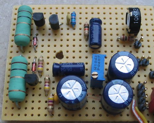
I thought it would be nice and trashy if the phone could make sound on its own, so I searched for a simple amplifier cirquit. I found this one (german page). It delivers enough power to drive a small speaker. At the moment, I´m using a little PC beeper speaker that sounds really trashy, but there´s a bit more room above the vocoder (behind the grill on the panel), so I will order a larger speaker soon. The speaker is of cause deactivated when a cable is plugged into the audio out. Here´s the amp:
and the whole amp/bypass board in its current state:
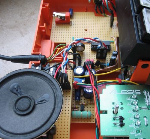
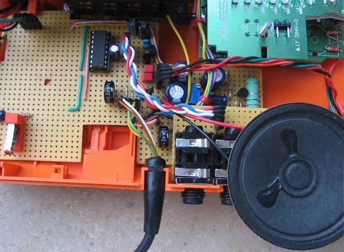
everything connected:
To be continued 

