This is an old revision of the document!
Table of Contents
Control Panel AIN_4 & AOUT_4 v1.2
AIN4 - AOUT4 v1.2 TOP

BOM:
8x Switch better take mouser ones...
LED5-8: Normal LEDs
LED1-4: Bipolar LED comman Anode
VR1-4 AOUT4: 10K Lin
VR1-4 AIN4: 100K Lin
SKT1-4: 3,5 Stereo Jack?
JP21: Clock Input(if you have, then dont set G1_G5 on the backside)
J1: Gate/DOUT/Clock - Input - pinout see DOUTx4-Board
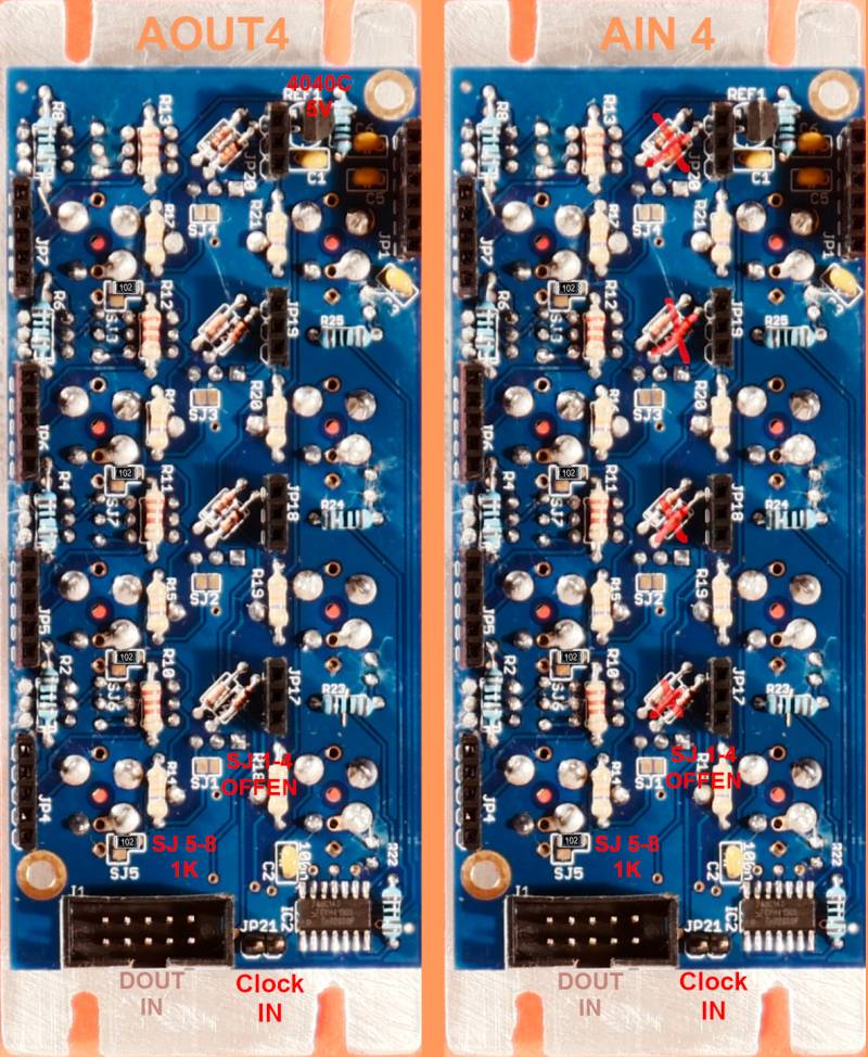
AIN_4 v1.2 BACK

BOM:
RN1: 100k iso 652-4816P-1LF-100K
SJ 1-4: let them unsoldered
SJ 5-8: solder a 1K 0603 SMD Resistor from the Round PAD to 5V- to avoid Floating
Diodes: 1N4148 > only Stuff in AOUT4 Usecases
IC2: 74LV14H (SOIC14)
C2: 100nF Kerko
The Rest: cant remember…Resistors and Caps…
about G5_G1, G2_G6, G4_G8, G7_G3 latigid on says:
Es wurde DOUT Gates/Clocks da rechts abzuschliessen gedacht. Es gibt aber nur 4x Ausgänge. In Effekt kannst du deine Signale ein bzw. aus an J1 routen (siehe mal das DOUTX4 Pinout).
Zusätzlich kannst du eine Clock einbringen, die wird zweimal gepuffert und kommt aus J21.
In diesem Fall keine Brücke bei G1_G5 setzen!


