Table of Contents
EASY CV
Test Equipment: CV-Destination MB33 MAM:

Introduction
All Parameters are saved as a preset as a song (programchange…)
Digital created LFO+ENV with CV-Output.
No Displays, No Menues, Minimal buttons, much Scopes, much Led-Ring-Rotarys (LRE-8x2CS)
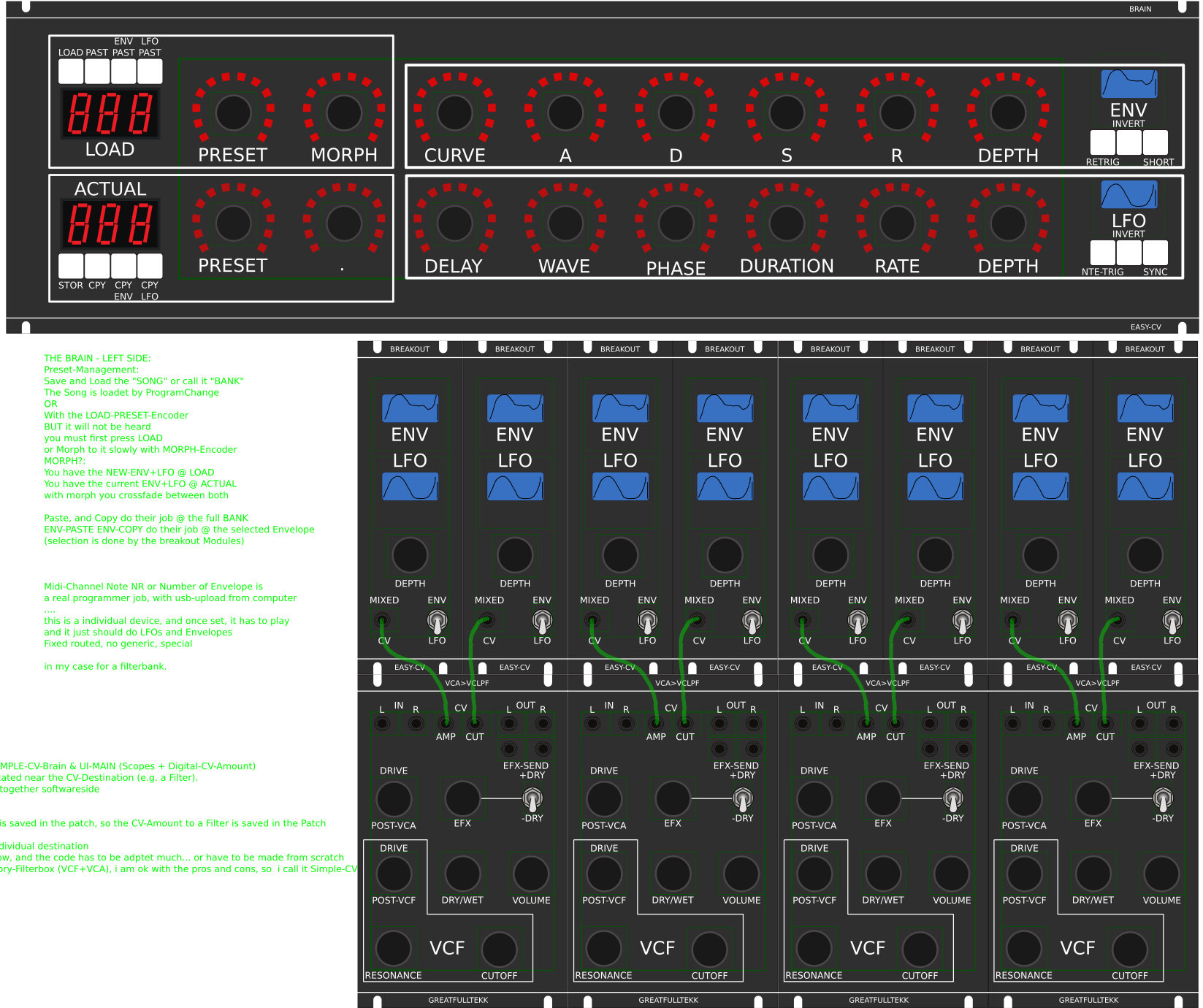
one big UI with complete functions for one LFO+ENV Voice + 4xChannelstrip Controlls…
LFO+ENV are mixed together softwareside, to use only one CV-Output
Each Channel = Filter need 8xCV-Outputs
Copy Paste for LFOs and ENVelopes between the Voices
Copy Paste for a Song aka Preset aka Bank aka Program(change)
Jam Style Pattern load (next Preset Display) + Preset Morph between Current-Preset and Next-Preset
The Early Design was a EuroRack-Module: A Breakoutmodule for each CV-Output, with Depth-rotary, Focusswitch (Pushrotary), 2x Scopes (LFO+ENV) and LFO/ENV-Switch to show on one Display the Mixed Waveform & to switch the Rotary to “ENV” or “LFO” Mode (there is only space for one Encoder - maybe just make PAN Style, instead of 2 individual level -maybe more live feel?, how ever when using an 3Stage switch, i could disable MIX-View, or display it on ENV or LFO…maybe a good choise ;) ) The Depth-rotary has no Ledring, want to display it as a bar or as Value in the scope…
FrontPanel
Brain
THE LEFT SIDE of the BRAIN > Preset-Management:
Save & Load the PROGRAM, can be done by Midi-ProgramChange -or With the LOAD-PRESET-Encoder
then press LOAD -or Morph to the next Program slowly with the MORPH-Encoder
-Another option is to take a PUSH-ENCODER for LOAD & STORE > and load and store it by pushing it… would free 2 buttons for other functions.
MORPH?:
-The Upper 7 Segment LED- Display: is the LOAD Display indicate the new Program with ENV+LFO
-The downer7 Segment LED- Dsipaly: is the STORE Display it indicates also the current Program with ENV+LFO
–with morph you crossfade between both Presets (be carefull, first Store the current Preset
Paste & Copy do their job @ the whole PROGRAM Memory
ENV-PASTE & ENV-COPY do their job @ the selected Envelope > (ENV-Voice selection is done by the breakout Modules) … LFO..same
Midi-Channel Note NR or Number of Envelope is a real programmer job (C), with usb-upload from computer
…. this is a individual device, and once set, it has to play > and it just should do LFOs and Envelopes
Fixed routed, no generic, special > in my case for a filterbank.
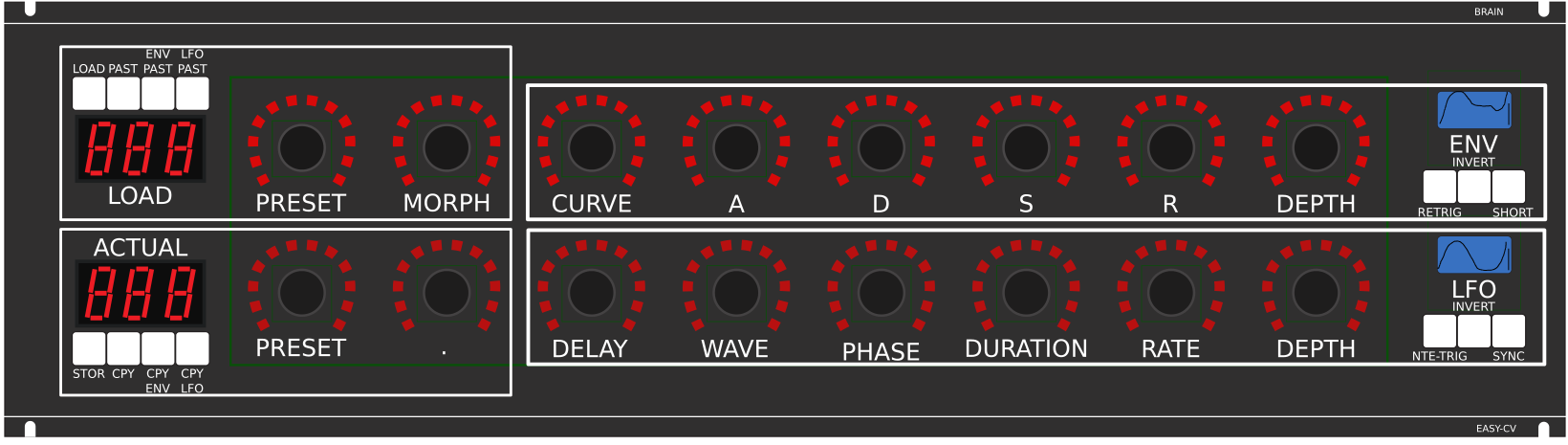 THE RIGHT SIDE of the BRAIN > LFO + ENV Settings (one Voice):
ADSR with:
THE RIGHT SIDE of the BRAIN > LFO + ENV Settings (one Voice):
ADSR with:
CURVE Paremter which give exponentially to it (no straight lines While Fall and Rise)
Short: just shorten the Maximal lenght of a Envelope, haveing more Feeling on Encoders
should change Scope Display also…
LFO: get synced with Midi, and there is a retrigger by Notes…
Phase: offsets the start-Phase
Delay: simple delay (nte-Trig)
Rate: clear from 8 wholes to 128th or so
Wave: access to the Waveforms
Duration: interpret Midisync in trippled, whole notes or whatever…
DEPTH: is the maximal Value of FALL and RISE and SUSTAIN, i know i loose resolution with this…but i have to have a memory filterbank,…doing depth instead with Potentiometers on Filtermodules… would give no memory…
BreakOut
this will not be supportet > since i dont want a Euro-Module Setup > i want one big filterbox.
1. Discharged UserInterface for the Brain in “Island mode” (Scopes + Digital-CV-Amount)
2. CV-Breakout EuroModule to be located near the CV-Destination (example: a Filter).
2 Waveforms (ENV+LFO) are mixed together softwareside
that bring 2 advanteges:
1.save one CV-Output
2. the Amplitude of each Waveform is saved in the patch, so the CV-Amount to a Filter is saved in the Patch
That bring 2 disadvanteges:
1.LFO or ENV cant get patched to individual destination
2.the Resulution gets lower 2 very low, and the code has to be adptet much… or have to be made from scratch
Because I use the device for a Memory-Filterbox (VCF+VCA), i am ok with the pros and cons, so i call it EASY-CV
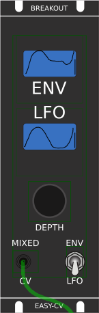 Envelope Scope: show the ENV-Waveform
or the Mixed-CV-Output-Waveform (when Switch is in LFO Mode)
and show the Envelope-Amount with a BAR or as numeric Value?
MIXED CV Plug: CV-Output > Mixed Waveform ENV+LFO
Switch @ ENV:
- Depth-Encoder change ENV Amount of the CV-MIX
- ENV Scope will show ENV Wave
- LFO Scope will Show CV-Mix
Switch @ LFO: visa versa ENV
Press the Encoders built in ENCODER-BUTTON:
will switch the BRAIN-A-D-S-R and L-F-O ENCODER to the Page for THIS Module…
workflow, see what you have with a Scope, over a filter, and edit exact this selected CV on the brain in full detail…
VCA-VCF
CVś(AOUT):
1.VCF-CUT
2.VCF-RES
3.FILTER DRIVE
4.VCA-ENV
5.VCA-DRIVE
6.DRY-WET (Orginal vs Filtered Mixer)
7.Send 2 EFX1
8.Send 2 EFX2
So 1x 8AOUT-Module for each “Channelstrip”, makes a total of 4x8AOUT-Modules.
The Module of Choise is a 16Bit, since i control with the the same AOUT-Channel ENV+CUT-OFF…
so there is no analog potentiometer for Cutoff or resonance… it is all saved in the Preset.
the VCA is basicly a simple VCA (MS20Like) or something
the VCF are a 303 18dB for the 24db Filter it will be a SSM2044, where bords are available.
In order to not use those overprized MATCHED-PAIR-TRANSISTORS (over 2€ on the cheapest place) i have to use standart Transistors and make a VBE-MATCH on my own, i have already a PCB from here - to measure the transistors with a Multimeter: https://midisizer.com/other/vbe-matching/
Example for a Filterbank
EUROMODULE-BASED »> It is not planed to do it that way (just for you to get some input)
A not EUROMODULE-BASED Version of something like this is the FILTERBOX:
(this is the Design I prefer @ the moment)

Filterbox OneChannel > first idea of Block-shematic:

General Design
The Panel is made of transparent but shadet (black transparent) Plexiglass.
The Panel is directly mounted into a Flightcase.
The 3x LRE8x2 (LEDRING) are mounted with the Encoder Nuts, the rest of the PCBs are mounted with normal thruhole screws.
FrontPanel
PCBs
The Analog-IO Board on the Backpanel, holds:
-the ENV-VCAs
-the DryWet-VCAs, Filter-Releay-Switch
-SEND-EFX-VCAs
-the Summing Mixer
-the Ducking-Cross-AMP-Follower+Ducking-VCAs
-VCF+ENV-VCA-Distortion-Driver-VCAs
-the Connectors to connect the Filter, AOUT, Poti-Boards
Left-Part of the Brain on Breathboard:
OLED-Display
Button: ShadowSE/ITT
ENCODER: with built in Pushswitch
a early state with 7Segment Displays to indicate the Patches

1. UI Parts Listing
BRAIN + BREAKOUT
- 6,3 Neutrik Connector
| Value | Type | Qty |
|---|---|---|
| Switch | SPDT Vertical PCB-Mount ON-OFF-ON | 1 |
 Fill Table
Pots / Knobs
- which Values for the Audio-Mixer?
3.Footprint Making in KiCAD
- ALPS Pots
- Alpha Pots
- 6,3mm Jack
- Switch
- Momentary Switch
- SSD-Displays
- OLED DIsplay
- Rotary Encoder
have to be done
4. Schematics in KiCAD
have to be done
5.PCB Making In Kicad
PCB Making Order
- BRAIN PCBs:
a.Left-Brain
b.Right-Brain
- 3x LRE8x2CS - is a generic PCB which i already have (fairlightiiś)
- Backpanel PCB
- FILTER PCBs