Table of Contents
Standard 220mm wide Modules
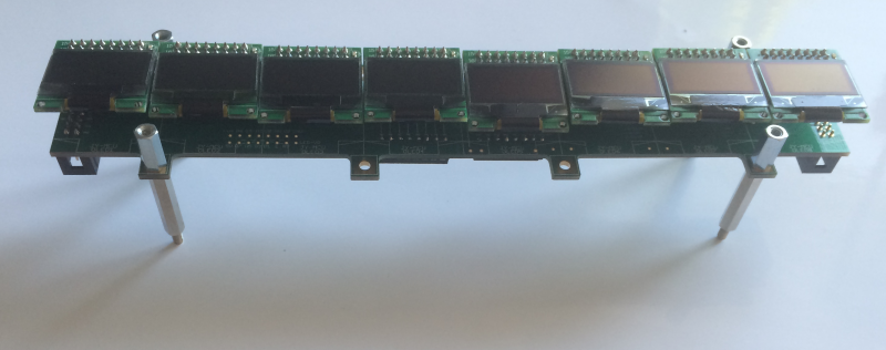
VLR-8oDisp
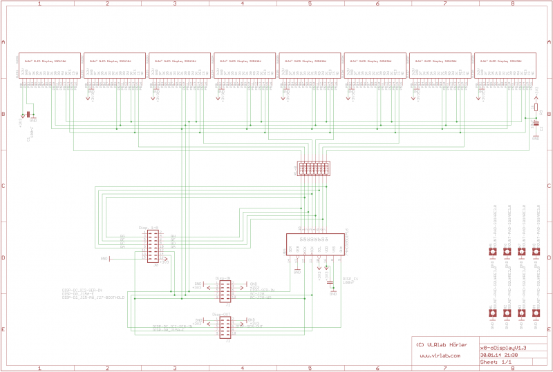
A PCB for chaning up to 32 OLEDs on 4×8 OLED Modules.
It can be connected to the RTPMIDI-CORE-STM32F4 from BEB DigitalAudio.
The Thread about that cool piece of Hardware is here: http://midibox.org/forums/topic/18526-midibox-goes-rtp-midi/
And you can Order his parts directly over his contact formula on the site:http://beb.digitalaudio.free.fr/contact.html

Eagle Files: https://github.com/novski/Midibox/tree/master/VLR-8Disp
BOM
BIll of Material
Allways look for the cheapest seller, the Price may vary heavy!!! And look for Local dealers preferred. http://www.midibox.org/dokuwiki/doku.php?id=where_to_order_components
The OLEDs
I got those displays from this dealer: http://www.aliexpress.com/snapshot/207517549.html
The other Materials: Mouser
- 2x10pin Header, 517-30310-6002
- 1x16pin Header, 517-30316-6002
- 2x16Pin DIP, 571-1-390261-4
- 1xResistor Array 220Ohm, 652-4116R-1LF-220
- 1x74HC595, 595-SN74HC595N
- 2x100nF, 505-MKS2.1/63/5
- 1x100uF, 667-ECE-A1EKA100
- 1x1kOhm, 660-MF1/4DCT52A1001F
- 8xFemale Header, 649-66953-008
Project Order Basket on Mouser: http://www.mouser.com/ProjectManager/ProjectDetail.aspx?AccessID=0c73d90bd5
The PCB is available under: https://vlrlab.com/pcb/10-8-odisplay.html
How to get Started
You will need to set the Connection of the Display.
So all 3 Code Resistors need to be on the Left side…
If you don't like the LED on top you can de-solder it now.
Prepare the PCB
The first PCB gets its Selection Lines from the Display Connection J15A on the Core PCB. So you will need to solder the 16Pin Header at this Panel. Here you can leave out the 10pin Headers and the IC Socket for the Shift register, if you like.
The Second PCB for Display 9-16 gets its Selection lines from the Shift register and doesn't need the 16pin Header so you have to solder J1 and J2 but you can leave out J0.
For both use cases you need to stuff the Resistor array so its best to solder a 16pin IC-Socket and stuff it in that.
PCB 3&4 are same as the second.
Prepare the Connection
Test it in MIOS
This is a Test file for Mios:
RESET_HW
LCD “%C”
LCD “@(1:1:1)OLED1”
LCD “@(2:1:1)OLED2”
LCD “@(3:1:1)OLED3”
LCD “@(4:1:1)OLED4”
LCD “@(5:1:1)OLED5”
LCD “@(6:1:1)OLED6”
LCD “@(7:1:1)OLED7”
LCD “@(8:1:1)OLED8”
LCD “@(9:1:1)OLED9”
LCD “@(10:1:1)OLED10”
LCD “@(11:1:1)OLED11”
LCD “@(12:1:1)OLED12”
LCD “@(13:1:1)OLED13”
LCD “@(14:1:1)OLED14”
LCD “@(15:1:1)OLED15”
LCD “@(16:1:1)OLED16”
LCD “@(17:1:1)OLED17”
LCD “@(18:1:1)OLED18”
LCD “@(19:1:1)OLED19”
LCD “@(20:1:1)OLED20”
LCD “@(21:1:1)OLED21”
LCD “@(22:1:1)OLED22”
LCD “@(23:1:1)OLED23”
LCD “@(24:1:1)OLED24”
LCD “@(25:1:1)OLED25”
LCD “@(26:1:1)OLED26”
LCD “@(27:1:1)OLED27”
LCD “@(28:1:1)OLED28”
LCD “@(29:1:1)OLED29”
LCD “@(30:1:1)OLED30”
LCD “@(31:1:1)OLED31”
LCD “@(32:1:1)OLED32”


