Table of Contents
GM5x5x5 Module
BEFORE YOU START SOLDERING CHECK THE ERRATA PAGE
This page is dedicated to nILS' standalone GM5 USB-To-Midi PCB. All information present on and files linked to from this site is
© 2008 nILS Podewski. Free for private, non-commercial use. All other rights reserved.
Related pages:
PCB revisions
- Prototype: Green PCB
- Bulk order #1, revision 1.0: White PCB
- Bulk order #2, revision 1.1: Red PCB
PCB overview
The PCB is 8.8 x 1.925 inches (~22.4 x 4.9 cm) looks like this:
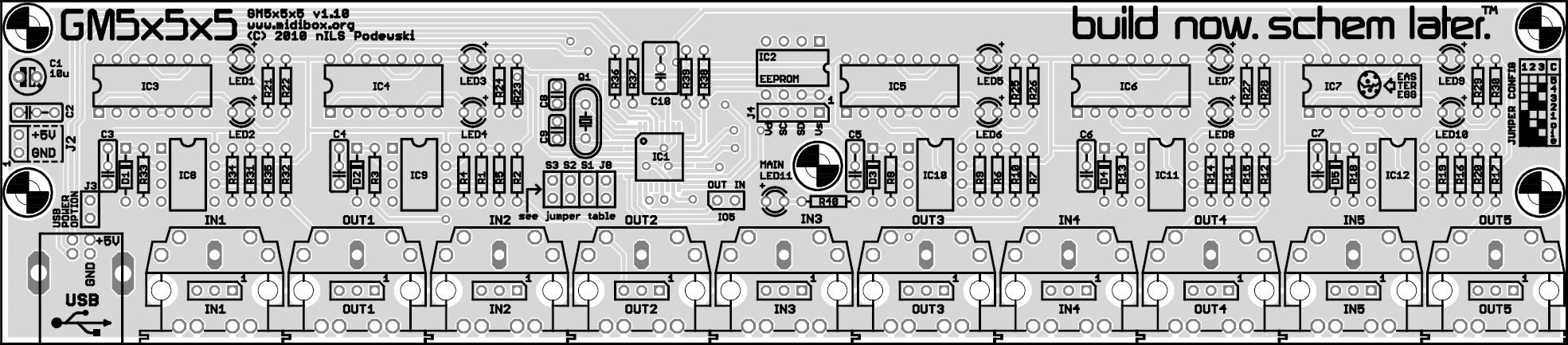
(click for full size)
A .pdf version is available here
A .pdf version with both layers visible is available here
Connectors
| Name | Number of pins | Description |
| J1 | 4 | USB connector |
| J2 | 2 | +5V in-/output |
| J4 | 4 | Interface to a core modules J4 port. Serves as an in-circuit programmer for the EEPROM - only use this port, when the gm5x5x5 is not plugged into a USB port |
| J8 | 2 | Configuration Jumper. Closed (default): midibox.org configuration, open: ploytec.com configuration |
| S1, S2, S3 | 2 | Configuration jumpers. See table in the schematic on ucapps.de or check the silkscreen. If you are not using an EEPROM you must set jumpers here, otherwise the gm5 will not be initialized properly |
| IN1 – IN5 | 3 (2 used) | MIDI In Jacks (opto isolated), both available as 1×3 pin header and DIN5 socket |
| OUT1 – OUT5 | 3 | MIDI Out Jacks, both available as 1×3 pin header and DIN5 socket |
| IO5 | 2 | Digital MIDI IO (mainly for development) |
| USB POWER OPTION | 2 | Configuration jumper. Closed (jumper mounted): gm5 powered by USB (recommended). Open (no jumper mounted): gm5 powered by +5VDC via J2 |
Part list / BOM
 Note that some resistor designators have changed in revision 1.1!
| Part | Value | Count | Footprint/ lead spacing | Part # |
| Crystal | 16Mhz | 1 | HC18/U | Q1 |
| LED 3mm | - | 11 | - | LED1 – LED11 |
| Diode | 1N4148 | 5 | - | D1 – D5 |
| Optocoupler | 6N138 | 5 | DIP 8 | IC8 – IC12 |
| GM5 | GM5 | 1 | TQFP32 | IC1 |
| Hex inverter(*2) | 74HC14 | 5 | DIP 14 | IC3 – IC7 |
| USB Type B socket | - | 1 | - | J1 |
| DIN 5 (MIDI) socket | - | 10 | MAB5SH | IN1 – IN5, OUT1 – OUT5 |
| 3-pin SIL header | - | 10 | 100 mil | IN1 – IN5, OUT1 – OUT5 |
| 2-pin SIL header | - | 5 | 100 mil | J2, J8, S1 – S3 |
| EEPROM | 24C04 | 1 | DIP8 | IC2 |
| Resistor (PCB rev 1.0) | 220 Ohm | 15 | 0207 | R1 – R3, R6 – R8, R11 – R13, R16, R18, R31 – R33, R39 |
| Resistor (PCB rev 1.1) | 220 Ohm | 15 | 0207 | R1 - R3, R6 - R8, R11 - R13, R16 - R18, R31 - R33 |
| Resistor (PCB rev 1.0) | 1k Ohm(*1) | 18 | 0207 | R5, R10, R15, R17, R20 - R30, R35, R38, R40 |
| Resistor (PCB rev 1.1) | 1k Ohm(*1) | 18 | 0207 | R5, R10, R15, R20 - R30, R35, R38 - R40 |
| Resistor | 27 Ohm | 2 | 0207 | R36, R37 |
| Resistor | 4.7k Ohm | 5 | 0207 | R4, R9, R14, R19, R34 |
| Polyfilm/Ceramic cap | 100nF | 6 | 200 mil | C2 – C7 |
| Electrolytic capacitor | 10uF/16V | 1 | 100 mil | C1 |
| Ceramic capacitor | 22pF | 2 | 100 mil | C8, C9 |
| Ceramic capacitor | 1uF | 1 | 100/200 mil | C10 |
| Jumper | - | 5 | 100 mil | - |
(*1) Note that 11 of the resistor listed as 1k in the above list (R21 - R30 and R40) are for the LEDs. The values for these resistors depends on the color of LEDs you plan to use and the brightness you wish to achieve. Suggested values:
| LED color | Value |
| red | 220-1k |
| yellow | 470-2k |
| green | 470-1k |
| blue | 1k-4.7k |
(*2) The inverters can be left out when no status LEDs are needed. Leaving them will require soldering some additional bridges which will be described in a section in this document later on.
Don't forget to order 6 DIP8 and 5 DIP14 IC sockets and pin headers (16 pins total).
Hardware Options
The pcb was designed to allow for various options:
1. Different numbers of IOs
You can use the jumpers S1-S3 or the EEPROM to select the number of devices the gm5 will run. If you decide to go with less than 5, you do not have to mount all the parts. The list below tells you which parts you can leave out per MIDI port. Notice that if you are not using an EEPROM you have to correctly set the jumpers otherwise the gm5 will not initialize properly.
| Port # not used | Parts to leave out |
| 5 | IC7, IC12, LED9, LED10, R16, R18, R19, R20, R29, R30, C7, D5, IN5, OUT5 |
| 4 | IC6, IC11, LED7, LED8, R11, R13, R14, R15, R27, R28, C6, D4, IN4, OUT4 |
| 3 | IC5, IC10, LED6, LED7, R6, R8, R9, R10, R25, R26, C5, D3, IN3, OUT3 |
| 2 | IC4, IC9, LED3, LED4, R1, R3, R4, R5, R23, R24, C4, D2, IN3, OUT3 |
2. (Not) using LEDs
If you want to use status LEDs, you will have to mount the 74HC14 hex inverters (IC3 - IC7) and the additional circuitry. If you do not want to use LEDs, you can leave out IC3 - IC7 and will have to add some jumper wires as follows. Instead of jumper wires you can easily use a 2-pin header and a jumper. Connect the following pins:
| Port # without LEDs | Wires to add |
| 5 | IC7:3 - IC7:2, IC7:10 - IC7:13 |
| 4 | IC6:3 - IC6:2, IC6:10 - IC6:13 |
| 3 | IC5:3 - IC5:2, IC5:10 - IC5:13 |
| 2 | IC4:3 - IC4:2, IC4:10 - IC4:13 |
| 1 | IC3:3 - IC3:2, IC3:10 - IC3:13 |
The additional LED circuitry can be left out of course, too:
| Port # without LEDs | Parts to leave out |
| 5 | IC7, R29, R30, LED9, LED10 |
| 4 | IC6, R27, R28, LED7, LED8 |
| 3 | IC5, R25, R26, LED5, LED6 |
| 2 | IC4, R23, R24, LED3, LED4 |
| 1 | IC3, R21, R22, LED1, LED2 |
Soldering info
All capacitors (except for the crystal bias caps) have a dual-footprint to allow for using 100mil or 200mil (2.54mm or 5.08mm) spaced capacitors. The image below shows how to mount either one. The first column shows the silkscreen you'll find for capacitors, while the second column shows the mounting position of 100mil (2.54mm) capacitors and the third column shows the mounting position of 200mil (5.08mm) capacitors.

Order lists
If you have an order list from a supplier that is not listed here, feel free to PM it to me, so it can be added to this page.
| Supplier | Price | Link | Comment |
| Reichelt | 12,37€ | https://secure.reichelt.de/?;ACTION=20;LA=5010;AWKID=121145;PROVID=2084 | misses the 1uF capacitor! |
| Mouser | 12,42€ | http://www.mouser.com/ProjectManager/ProjectDetail.aspx?AccessID=5faef11e59 | thanks to frailn. Updated by Grizz |
| Allied Electronics | $37.27 | GM5x5x5 - Allied Parts List | Put together by m00dawg |
FAQ - Frequently Asked Questions
Q: Can I have the .brd or .sch file?
A: No.
Q: There are no ground connections. Why?
A: There is a ground plane on the bottom (blue) layer, which is not visible in the screenshot and .pdf.
Q: Can I leave out the inverters?
A: Yes, you can if you do not wish to have status LEDs. If you decide to do so, you will need to add some bridges to the board as described in the “hardware options” section.
Q: My gm5x5x5 isn't working - LED11 is lit and my computer doesn't recognize the device. What's wrong?
A: Most likely you forgot to put the jumpers S1 - S3 on the PCB. Put them on there (see jumper table for jumper positions), plug the gm5x5x5 back into the PC. Doesn't work? Check the soldering.
Q: Can you tell me the positions of the holes and sockets?
A: Sure. The following list has all the positions of the sockets and the holes. All measurements are in mil (1/1000th inch) and give you the center of component/hole.
Mount holes
| x | y |
| 150 | 850 |
| 8650 | 850 |
| 150 | 1775 |
| 8650 | 1775 |
| 4590 | 1000 |
USB socket (x)
| 450 |
Midi sockets (x)
| 1200 |
| 2000 |
| 2800 |
| 3600 |
| 4400 |
| 5200 |
| 6000 |
| 6800 |
| 7600 |
| 8400 |