Table of Contents
Visual Metronome
Hi All,
I thought I would share a little project of mine.
At a recent show, there was a problem with the monitors leaving the rest of the band unable to hear the beat.
We normally use a click track but it was not possible at this show. This lead me to come up with this design for a visual metronome so the others know where we are in the bar.
I posted my original design in the forum, the reply from technobreath inspired me to redesign the project.
The project is now in 2 parts, a master unit and a slave. The master can be used as a midi clock master and a standalone midi & visual metronome.
The slave can be used with the master or with a sequencer or with your DAW's metronome output.
Version 02 has 32 preset memory locations to store the setup for quick recall.
The master hardware consists of
- PIC core
- DINx1
- DOUTx2
- 20×2 CLCD (HD44780)
- 5 buttons and 1 encoder on the control surface
- LEDs to suit the hardware options
The slave or remote unit consists of
- PIC core
- DOUTx1
- Custom logic board
- LEDs to suit the hardware options
Master Unit Design
Other than the LED options, the master is arranged the same as most other MB projects. Please refer to the pdf files for the wiring. If the master incorporates the large LED display no additional logic board is required, just refer to the slave unit LED schematic.
Core connections are here
DOUT pins are here
DIN pins are here
An explanation of the menu/display is here
The source code is available here
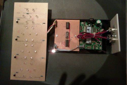
Here are some pictures of the master unit that I have built. The board is a home made version of the pic core along with a custom DOUTx2 DINx1 board. I had intended to separate the 2 boards but the whole panel fitted in the case so left them as one. I left several components out of the core part, only the parts required for this project are fitted. The unit is powered by a 5volt SMPS.
Slave Unit Design
The slave can be used with the master or any other source of midi metronome (note on/off) events. It does not require a midi clock.
The slave uses the MIDIO128 firmware (here) to receive the incoming midi notes, switching the DOUT pins as appropriate. See the programming pdf here.
What makes this device different is the large LED display that indicates the beat. In my design I have only used 4 steps with the 1st beat indicated by red LEDs, beats 2 & 3 are green and beat 4 is yellow (like traffic lights, yellow means “get ready”). Here is a little video that shows it in action https://www.youtube.com/watch?v=fA3AotthsEY
The blue LEDs give a visual reference for which beat is current and they look good too!
The heart of the slave is the logic board. The DOUT drives a CMOS decade counter (CD4017) via a CMOS OR gate (CD4071). The 1st OR gate combines the 2 note lines to the counter clock input and the 2nd gate combines the reset lines for the counter.
The decade counter does as the name implies. On every clock pulse the counter increments by 1, driving outputs Q0 to Q9 high one at a time. These outputs then drive a transistor to switch on the LEDs.
The reset line is connected to the next free output so that the counter resets after the required number of beats.
Example: 4 beats using Q0 to Q3, reset is on Q4
The firmware is set up to reset the counter when the first metronome beat of the bar is received, assuming that different notes are used for beat 1 and the rest of bar. If the metronome uses the same note then the hardware option must be used.
The logic board can be built on stripboard and can contain the DOUT circuit. There is no required layout, just make sure it is all connected as shown in the schematic here
The LED circuit is very simple, a single transistor as the switch, a couple of resistors and your choice of LEDs. I built the display on stripboard and chose an interesting layout for the LEDS. Link to pdf here
The core connections could not be simpler.


