midibox_pokey
Table of Contents
MIDIBox POKEY
Q: What is it?
A: A synth module for the MBHP based on the Atari POKEY (= POtentiometer and KEYboard) sound chip. It will eventually lead to a synth module like the SID or the OPL3 module.
Current Status
- 11/17/2007: More parts added → waiting for parts to get here, schem and board layout 90% done
- 10/23/2007: Parts for the mbPokey board have arrived. More soldering to do.
- 10/22/2007: POKEY → LPT board is working, software to control the POKEY with a PC is working as well
- 08/14/2008: PCB layout done, rudimentary MIDI→Pokey note application probably done, my pokey is most likely fried. Need to get a new one

TODO
- Documentation

- Check and finish layout of mbPokey board
- Port software to PIC
- Explore the possibilities
- Design and build a control surface (Step A)
- Multiple Pokeys (Step B)
- Full control surface (Step C)
===== POKEY (C012294) Specifications ====='

Taken from the datasheet:
- 4 semi-independent audio channels, each with its own frequency, noise and volume control. Each channel has an eight-bit “divide-by-N” frequency divider and an eight-bit control register (AUDFX). Each channel also has an eight-bit control register (AUDCX) which selects the noise (polynomial counter) content and the volume.
- All four frequency dividers can be clocked simultaneously from 64 kHz or 15 kHz by AUDCTL bit 0. Frequency dividers 1 and 3 can alternately be clocked from the CPU clock (1.79 MHz NTSC, 1.77 MHz PAL) by setting AUDCTL bits 5 and 6. Frequency dividers 2 and 4 can alternately be clocked with the output of dividers 1 and 3 by setting AUDCTL bits 4 and 3. This allows the following options: 4 channels of 8-bit resolution, 2 channels of 16-bit resolution, or 1 channel of 16-bit resolution and 2 channels of 8-bit resolution.
- There are three polynomial counters (17 bit, 5 bit and 4-bit) used to generate randowm noise. The 17-bit poly counter can be reduced to a 9-bit poly counter by bit 7 of AUDCTL. These counters are clocked byt 1.79 MHz. Their outputs, however, can be sampled independently by the four audio channels at a rate determined by each channel's frequency divider. Thus each channle appears to contain seperate poly counters clocked at its own frequency. This oly counter noise sampling is controlled by bits 5, 6 and 7 of each AUDCX register. Because the poly counters are sampled by the “divide-by-N” frequency divider, the output obviously cannot change faster than the sampling rate. In these modes (poly noise outputted), the dividers are therefore acting as “low-pass” filter clocks, allowing only the low-frequency noise to pass.
- The output of the noise-control circuit described above consists of pure tones (square wave type), or polynomial counter noise at a maximum frequency set by the “divide-by-N” counter (low pass clock). This output can be routed through a high-pass filter if desired by use of bits 1 and 2 of AUDCTL.
- The high-pass filter consists of a D-type flip-flop and an exclusive-OR gate. The noise control circuit output is sampled by this flip flop at a rate set by the “high-pass” clock. The input and output of the flip-flop pass through the exclusive-OR gate. However, if it is lower than the clock rate, the flip-flop output will tend to follow the input and the two exclusive-OR gate inputs will mostly be identical (11 or 00) givving very littl output. This gives the effect of a crude high-pass filter, passing only noise whose minimum frequency is set by the high-pass clock rate. Only channels 1 and 2 have such a high-pass filter. The high-pass clock for channel 1 comes from the channel 3 divider. The high-pass clock for channel 2 comes from the channel 4 divider. This filter is only included if bit 1 or 2 of AUDCTL is true.
- A volume control ciruit is placed at the output of each channel. This is a crude 4-bit digital to analog converter that allows sellection of one of 16 possible output current levels for a true audio input. A logic zero audio input to this voulme circuit always gives an open-circuit (zero current) output. The volume selection is controlled by bits 0 through 3 of AUDCX. “Volume Control only” mode can be invoked by forcing this circuit's audio input true with bit 4 of AUDCX. In this mode the dividers, noise counters, and filter circuits are all disconnected from the channel output. Only the volume control bits (0 to 3 of AUDCX) determine the channel output current.
- The audio output of any channel can be completely turned off by writing zero to the volume control bits of AUDCX. All ones give maximum volume.
Hardware
Preliminary schematics and boards
LPT -> POKEY schematic
- Allows to hook up a Pokey to a PC's printer port.
- This circuit uses a 1.77Mhz (PAL) or 1.79Mhz (NTSC) crystal. You can either use some sort of frequency divider to get that frequency or use a 1.8432Mhz crystal. This may lead to some issues though.
 Click for larger view
mbPokey schematic and board
- This is a beta version of what the circuit to be used in a MIDIBox environment.
- It would run on either a 3.579545Mhz crystal for NTSC or a 3.5486Mhz crystal for PAL
 Click for larger view
- This is a test version of the board. The size is a square of the short side of a core module.
 Click for larger view
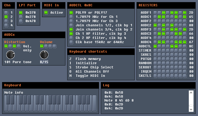
Software
Since I'm using the POKEY→LPT circuit at the moment, I'm wrote a tiny program that allows the user to directly manipulate the POKEY's registers. It's in early alpha and looks like this:
Links
Internal
- http://www.midibox.org/forum/index.php?topic=10026.0 - The forum thread to this project
- http://www.midibox.org/forum/index.php?topic=5043.0 - Forum thread “MIDIBOX Atari POKEY?”
- http://www.midibox.org/forum/index.php?topic=5431.0 - Forum thread “ATARI POKEY????”
External
- http://en.wikipedia.org/wiki/Atari_POKEY - Wikipedia entry for the POKEY chip (polish version is much more in-depth, but my polish isn't really all that good) (they seem to be in sync with the english version having a tiny bit more than the polish one as of right now - cheater)
- http://krap.pl/mirrorz/atari/homepage.ntlworld.com/kryten_droid/Atari/800XL/atari_hw/pokey.htm - HTML version of the datasheet of the Pokey. The original datasheet can be found on the web as well.
- http://www.hillsoftware.com/atari/index.html - Mike Hill's website. He's the guy who created the LPT-Pokey schem and wrote a DOS app for it (won't work on Windows obviously)
- http://www.pokey.nl/xoops/modules/books/index.php?op=viewarticle&artid=10 - Some information on what to do with the POKEY
- http://little-scale.blogspot.com/2008/01/soft-midi-pokey.html A MIDI→POKEY implementation
midibox_pokey.txt · Last modified: 2016/06/14 11:43 by psykhaze