USB-power module
This is a very simple board performing the following functions:
- USB B socket (main USB (slave) and +5V power)
- USB A socket (for USB host)
- Toggle switch for USB host
- 3.5mm jack for footswitch/gate or other input/output (audio?)
- Headers to draw +5V directly off the USB power buss.
Schematic
Both USB connectors are wired to the 1*5 J1 header via low-value resistors. There is a TVS diode on the underside that should help a bit with ESD. One side of the toggle switch sets the ID pin low, meaning the Core should respond as a USB host. In this case, it is expected that the USB B socket supplies power only. The host port would then be the USB A socket. J7 must be closed to supply power from the main USB buss to any slave device on the USB A side. If the slave has its own power supply, then leave J7 open.
Headers J3-6 are wired to +5V, so this is a good point to connect power-hungry parts like displays or LEDs.
The left-hand side connects to the 3.5mm socket. The idea is to use the tip of a stereo jack as an interface to a gate (i.e. from a modular synth). As the DIN pins normally expect negative-going signals, the classic S-trig converter is applied:
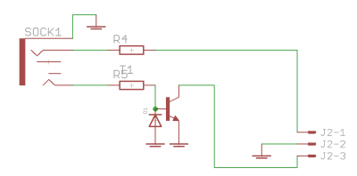
To use the socket for another purpose (audio input or output?), feel free to omit the diode and transistor, and to bridge the collector and base pins.
The ring of the socket is for a normal footswitch closing to 0V/ground and there is a protection resistor in series.
BOM v1.0
Please find the current BOM on http://midiphy.com. The table below is depreciated and will not be updated.
| Type | Qty | Value | Package | Parts | Mouser | Reichelt | Conrad | Other | Notes |
|---|---|---|---|---|---|---|---|---|---|
| Resistors | |||||||||
| 2 | 22R 5% | 1206 | R1, R2 | ||||||
| 1 | 330R 5% | 1206 | R3 | ||||||
| 2 | 10k 5% | THT | R4, R5 | ||||||
| Diodes | |||||||||
| 1 | 1N4148 | THT | |||||||
| 1 | TVS | SOT-143 | TVS1 | PRTR5V0U2X,215 | |||||
| Transistor | |||||||||
| 1 | BC337 | TO-92 | T1 | ||||||
| Switch | |||||||||
| 1 | SPDT | SW1 | 1101M2S3AV2BE2 | SS 13LSP | Mouser one is better quality | ||||
| 1101M2S4AV2BE2 | Longer actuator (recommended). | ||||||||
| Headers | |||||||||
| 1 | 1*2 | male | |||||||
| 5 | 1*3 | male | |||||||
| 1 | 1*5 | male | or wire directly | ||||||
| Sockets | |||||||||
| 1 | USB B | horizontal | USB1 | 538-67068-7041 | USB BW | ||||
| 1 | USB A | upright | USB2 | 538-89485-8000 | |||||
| 1 | 3.5mm | SOCK1 | CUI SJ1-3535NG | other variants are possible (different pins switched etc.) | |||||
| Hardware | |||||||||
| 2 | M3 PCB mount | 534-7695 | |||||||
Versions
v1.0: first release.
Assembly
Solder the SMT parts first. Ensure the TVS diode is aligned with the larger pin on the larger pad and that the wide edge of the body fits between the silkscreen indicators:

Note this is the board viewed from the bottom; the larger pin is on the bottom-left.
To have a through-hole USB A socket, the pins are quite close together. Be careful to avoid bridges when soldering and test with a multimeter to ensure no adjacent pins are connected afterwards!
It goes without saying, but ensure none of the metal parts are touching (e.g. the outside of the USB sockets with J7, the 1N4148 diode with the mounting brackets etc.).
License
Currently the design is © 2017 antilog devices with all rights reserved; all documentation is CC BY-NC-SA 3.0.