Table of Contents
AINSER64 Module
Introduction
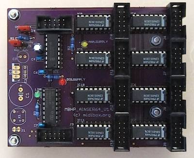
MBHP_AINSER64 is the successor of the MBHP_AIN module, and only supported by MIOS32!
It is based on the 8-channel ADC MCP3208 from Microchip and 8×4051 multiplexers so that up to 64 analog inputs are available. They can be used to scan pots and/or faders with 12bit resolution between 0 and 5V..The accuracy and especially the signal/noise ratio is much better compared to the internal ADCs of STM32 for insignificantly higher costs (around 3 EUR).
Another advantage is the Improved Scalability. While with the previous MBHP_AIN module the maximum number of scannable inputs was limited by the number of on-chip ADC channels, the new approach allows to access multiple MBHP_AINSER64 and MBHP_AINSER8 modules from the same microcontroller.The ADC is accessed via SPI (e.g. J19 of the MBHP_CORE_STM32F4 module).
Multiple MBHP_AINSER8 (or MBHP_AINSER64) modules are connected to J19 in parallel, and accessed by strobing dedicated chip select lines. J19 provides two chip selects (called “RC1” and “RC2”), if more modules should be scanned, common IO pins could be used for the same purpose (e.g. available at J5). Alternatively, AINSER* modules could be chained, or a 3-to-8 MUX could be used for accessing 8 modules via 3 IO pins of the microcontroller.
Accuracy: the on-chip ADCs of STM32 are jittering by at least +/- 16. Accordingly, the effective resolution which can be used for MIDI controller purposes is 10 bit. Such a high resolution is especially useful for PitchBender and NRPN messages.
Powering the module via USB (provided at J19 by the core module) is sufficient. It's recommended to use a “selfpowered” USB Hub like this one from Reichelt. It also decouples the power from the (noisy) PC supply, and allows to run the MIDIbox without a PC connection.
Parts List / Schematic
- SchematicUCapps
Inputs/ Outputs Port Table
| Port | Pins # | Description |
|---|---|---|
| J2 | 10 | Serial input which is usually connected to J19 of MBHP_CORE_STM32F4 module. |
| J3 | 10 | Serial output which could be used to chain multiple MBHP_AINSER* modules.Please note: the standard AINSER driver for MIOS32 doesn't support this method! Instead it expects that multiple modules are connected to J19 in parallel, and that they are using dedicated chip select lines (selected via jumper J4)! |
| J4 | 3 | A jumper has to be connected to this port to select the first or second chip select line of J2 for accessing the ADC. |
| J6-J13 | 10 | 8×8 analog inputs and 5V (=Vd) / Ground (=Vs) connections.Please note: all unused analog inputs have to be clamped to ground (Vss), otherwise your MIDIbox will send out a lot of random MIDI events |

