Table of Contents
AOUT_NG

Introduction
The AOUT_NG is a CV (control voltage) output module. It features 8 channels of 12 bit CV out and a selectable bipolar option.
This module is an officially supported MBHP module, created by Thomas Stoeckl (Seppoman). Note that the AOUT_NG is not supposed to replace the existing AOUT module. The AOUT will continue to be supported and co-exist with the AOUT_NG. The need for a new design originated from both the high price and the bad availability of the MAX525 DACs used on the AOUT.
License
Like with everything else on uCApps/Midibox, you are not allowed to use this PCB in commercial designs without express permission by TK (for firmware and other modules) and Seppoman (AOUT_NG)!
Who needs which?
There are 3 different AOUT modules to be chosen from, so which one do you need?
The AOUT features 8 channels of 12 bit plus two additional gate outs. The MAX525 DACs feature a sightly better performance than the one used on the NG. So for perfectionists wanting to drive analog VCOs with maximum tuning precision, the AOUT is the right choice. Bipolar operation is possible but needs some external parts. As stated before, the MAX525 is quite expensive and hard to get, so only choose this module if you really know why you need it.
The AOUT_LC is the “entry-level” option. Very cheap, only two channels, configurable to either 12 bit and 4 bit or both 8 bit resolution. It is suitable for e.g. adding a VCF to a MBSID with only one SID channel at the lowest cost. If you only need a few CV channels, you can choose this one. Cascading of up to 4 AOUT_LC modules for a total of 8 channels is possible with MBFM and MBSID V2 but leads to increased preformance load because all AOUT channels need to be updated with each CV value change. Be aware that matching and soldering all the resistors needs quite a lot of time and that the achievable precision is usually worse than that of the NG. Building more than one or two AOUT_LCs doesn't make much sense because the cost will be in the same league as one AOUT_NG and with the NG you'll have better performance, flexibility and less work.
The AOUT_NG features very good performance and flexibility for a reasonable cost. As of now, it is the only module with a dual layered pro-made PCB (available from SmashTV, PCB only or as a full kit) that saves you from soldering any jumper wires. The bipolar option, although not very often needed, is a nice to have option and will e.g. be necessary for using Seppoman's SSM2044 module. The featured precision is perfect for controlling analog filters, VCAs etc. Despite the slightly inferior specs of the DAC, some real world tests confirmed that the precision is even sufficient to drive VCOs. So as long as you don't require extraordinary precision and saving a few bucks isn't your central aim, the NG will be the right choice. The only “drawback” is that the used DAC is only available as SOIC SMD part, so soldering it is not for absolute beginners. Don't be afraid though - with the right technique, SMD is really no problem - a nice tutorial video can be found here.
Where to buy?
SmashTV offers both the PCB and a full kit (including the DAC and the parts for bipolar option) in his shop.
Other places to buy parts:
TLV5630IDW
this is the only difficult to get part - the rest is available at every good electronics shop.
| Shop | Order Code | Price | Date Price Checked |
|---|---|---|---|
| Europe: | |||
| Farnell | 8455775 | 16.80 EUR + VAT | (2012/04/20) |
| USA: | |||
| Mouser | 595-TLV5630IDW | 21.10 USD | (2012/04/20) |
| Digikey | 296-3065-5-ND | 21.10 USD | (2012/04/20) |
| Newark | 38K8492 | 28.14 USD | (2012/04/20) |
| Canada: | |||
| Digikey | 296-3065-5-ND | 22.61 CAD | (2012/04/20) |
Note that Farnell only delivers to professional customers and university members.
Parts List
| Name | Part | Value | Quantity | Reichelt Order Code | Mouser |
|---|---|---|---|---|---|
| Regular Parts | |||||
| C1,C2 | Electrolytic Capacitor | 47uF | 2 | RAD 105 47/35 | 140-REA470M1CBK0511P |
| C3 | Electrolytic Capacitor | 10uF | 1 | RAD 105 10/63 | 140-RGA100M1VBK0511G |
| C4-C10 | Capacitor | 100nF | 7 | Z5U-2,5 100N | 594-A104K15X7RF5UAA |
| IC1 | D/A Converter | TLV5630 | 1 | not available | 595-TLV5630IDW |
| IC3,IC4 | OpAmp | TL074 | 2 | TL 074 DIL | 595-TL074IN |
| Sockets for OpAmps | 14-pin | 2 | GS 14 | 571-1-2199298-3 | |
| J1,J2 | Pin Header Single Row | none | 2 | see below | 855-M20-9994045 |
| J3,J4 | Pin Header Single Row | none | 2 | see below | 855-M20-9994045 |
| JP1,JP2,J5 | Pin Header Dual Row | none | 3 | see below | 571-5-146254-8 |
| LED1 | LED 3 mm | none | 1 | LED 3MM GN | 604-WP132XID |
| P1-P8 | Precision Trimpot(64Y) | 5k | 8 | 64Y-5,0k | 594-64Y502 |
| R1-R8 | Metal Film Resistor 1% | 27k | 8 | METALL 27,0K | 594-MBB02070C2702FC1 |
| R9-R16 | Metal Film Resistor 1% | 15k | 8 | METALL 15,0K | 594-MBB02070C1502FC1 |
| R49 | Resistor | 470 | 1 | METALL 470 | 71-CCF07470RGKE36 |
| (for R49, a standard resistor can also be used) | |||||
| Additional Parts for the Bipolar Option: | |||||
| P9-P16 | Precision Trimpot(64Y) | 200 | 8 | 64Y-200 | 594-64Y201 |
| R17-R32 | Metal Film Resistor 1% | 10k | 16 | METALL 10,0K | 594-MBB02070C1002FC1 |
| R33-R40 | Metal Film Resistor 1% | 2.2k | 8 | METALL 2,20K | 594-MBB02070C2201FC1 |
| R41-R48 | Metal Film Resistor 1% | 1.5k | 8 | METALL 1,50K | 594-MBB02070C1501FC1 |
Other Parts:
For the Js and JPs: one each of “SL 1X40G 2,54” and “SL 2x40G 2,54”
Jumpers: 8x or 16x “JUMPER 2,54 RT”
Reichelt Shopping Basket Links:
AOUT_NG without bipolar option - total 7.78 EUR
AOUT_NG with bipolar option - total 14.61 EUR
Feel free to add/update the above lists if you find other sources for the TLV or you've composed an order list for other shops (like Mouser, Digikey etc).
The PCB
In the center, there's the D/A converter and a power LED (signaling power on the 5V rail). The upper area contains the output amplifiers (TL074). Output gain can be adjusted with the trimmers P1-P8. On both sides of the DAC, there's the bipolar option. On JP1 and JP2, you can select unipolar or bipolar mode for each channel. The zero offset in bipolar mode is adjusted with P9-P16.
Files
 Quick View, Click for larger view
Software Support
Currently, the following application support the AOUT_NG:
Options
The bipolar option is, like the name implies, optional. I'd recommend to add it anyway as the needed parts are not very expensive. If one needs it later, it's less hassle to only change a few jumpers than to disconnect and remove the board, start soldering again and reconnect everything. If you really don't want the bipolar option, you can leave out P9-P16 and R17-R48. But as long as you have bought SmashTV's kit, you've got the needed parts anyway.
There are also pin- and software-compatible versions of the DAC with lower resolution. Although I don't recommend it, if you're definitely sure that lower resolution is sufficient for your needs, you can replace the TLV5630 with a TLV5631 (10 bit) or TLV5632 (8 bit). This change can be done without any other software/hardware modifications and you can save 5-10 bucks by doing it. But normally I don't think the saved money should be worth the sacrifice in precision. With lower resolution, a noticeable steppiness in e.g. the VCF cutoff frequency will occur, so think twice before not using the (normal) TLV5630!
Connectors
J1: data connection to the core. The pin assignment is the same as on the AOUT module. For connection to MBSID, the blue lines on this link show the necessary connections.
J2: data connection to subsequent AOUT_NGs when more than one module is chained (currently there's no application that makes use of this feature)
J3: Analog power in (+12V/GND/-12V). Take care of the orientation or you'll damage something!
J4: auxiliary analog power out, e.g. for powering a connected VCF
J5: CV out. Bottom row are the 8 control voltages, upper row is GND.

For connecting to a 32-bit Core a special ribbon cable must be prepared when using standard 2*5 IDCs:
Pin mapping:
| Core (STM/LPC) | AOUT_NG | |
|---|---|---|
| Pin | J19 (top row) | J1 |
| 1 | Vs | Vs |
| 2 | Vd | Vd |
| 3 | SO | CS(=RC) |
| 4 | SC | SI |
| 5 | RC1 | SC |
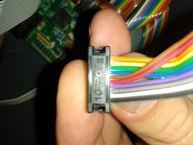
Wire the Core end 1:1 and connect to J19. Note pin 1 is on the bottom left, on the same side as the polarising notch. Take wires 9 and 10 (red and brown in this image) and insert them between wires 4 and 5 (purple and blue in this image). Shift wires 5-8 over so 5→7, 6→8 etc.
When clamping the connector shut, make sure the wires are straight with no unintended short circuits (0V, +5V and SC use two pins each). Check the Core schematic to be certain.
http://www.ucapps.de/mbhp/mbhp_core_stm32f4.pdf
http://www.ucapps.de/mbhp/mbhp_core_lpc17.pdf
Soldering
Like with any other module, it is good practice to solder the components from flat to high. This means: First solder the TLV5630 (carefully inspect the IC that there are no shorts between the narrow legs! Use a magnifying glass if you have one). Then solder R49 and the LED, the 100nF capacitors, chip sockets, the other resistors, pin headers, trimmers and finally the electrolytic capacitors. When you're finished, carefully inspect the board for shorts, bad solder joints etc.
Configuration
Jumpers:

By setting jumpers on JP1 and JP2, you can select normal or bipolar operation for each CV channel. When setting two jumpers like on channel 1 of the picture above, the channel is in bipolar mode. Channel 2 in the picture is in normal mode. Please select one mode for every channel, even for channels you won't use! If you have left out the parts for the bipolar option, you can solder bridges instead of the horizontal jumpers.
First Test
As the most expensive part on the module (the DAC) is already soldered to the board, visual inspection before powering up is more important than on other modules! So double-check all solder joints again before proceeding. You can leave out the TL074s for a first test. Then connect J1 to the core. Power up your Midibox. If the LED doesn't light up, IMMEDIATELY switch off power and re-check all connections and soldering. If you've connected J1 the wrong way, the LED could still light up (dimmer than normal), and the TLV5630 start to get increasingly hot, possibly damaging it after a while. If the LED is on, you can now connect analog power (+/- 12V) to J3. Make sure you have the right polarity or else you will blow up C1 and C2! If the analog PSU is the same as the one used for the rest of the Midibox (i.e. 5V and +/- 12V already have the same ground potential), don't connect ground to J3 to avoid ground loops. Then measure the voltages between pin 4 and GND (should be +12V) and pin 11 and GND (should be -12V) on the sockets of IC3 and IC4. When everything is ok, power down the box, install IC3 and IC4 to their sockets. Then power up again and recheck all voltages. Congratulations, your AOUT_NG is up and running :)
Calibration
Calibration of the outputs is necessary to achieve good results and interchangeability. In unipolar mode, the output gain can be adjusted with the trimpots P1..P8. Additionally, in bipolar mode, P9..P16 are used to adjust zero offset.
Midibox SID
First recompile the MB-SID firmware to use the AOUT_NG (i.e. #define AOUT_INTERFACE_TYPE 3). The default .hex files in the firmware distribution may not have this setting.
Select the default “Lead Patch” (or another patch where Ex1..Ex8 are NOT used as a modulation target!). Then go to the Ensemble→EXT menu page and make sure that F2A, V2A and Iv1..Iv8 are all disabled. This is necessary to get access to the full output value range. Set all jumpers to unipolar mode (see Configuration).
Now connect ground (black) of your multimeter to a GND pin of the AOUT_NG and the positive probe (usually red) to the first CV channel. If you have some, use croco clip wires for the connection so you don't need to hold the probes all the time :). Then go to the EXT menu of the MBSID patch. You'll see a 3 digit hex value indicating the current output value for each channel. The default value is 800. Set the channel value to FFF. Then adjust P1 until your multimeter reads 10.67 V. If the best possible tuning precision over the whole range is desired, you can additionally check some more voltages: A value of 180 should give 1V, 300=2V, 600=4V and C00=8V. A perfect match for all of them is normally not possible, but you can try to set the gain to have the average deviation as small as it can get.
If you have built the NG with bipolar option, now set the jumper of the channel to bipolar mode. Set the value to 800 and adjust P9 until the measurement reads 0V.
Repeat the above procedure for the other 7 channels.
Midibox SEQ V3
For Seq V3, recompile the MB-SEQ3 firmware to use the AOUT_NG (i.e. #define AOUT_INTERFACE_TYPE 3). The default .hex files in the firmware distribution may not have this setting.
Some explanations : Analog synths use a Gate and a CV inputs to produce tone from their VCO. The Gate signal will trig the tone while the CV will set the Pitch (the heignt of the note in musical terms).
Some synths use a CV range from 0 to 10,67V to pitch ; that's the UNIPOLAR mode (e.g Roland).
Others use a CV range from -5V to +5V to pitch ; that's the BIPOLAR mode (e.g Moog). Have a look in the manual to know what does your synth (e.g Moog Voyager use bipolar CV for its VCO pitch)
The following process apply to synth in V/oct (Korg synths use Hz/volt for example, but it is another story) :
Set the 1st jumper to unipolar mode (see Configuration). You will calibrate the 1st CV channel
Select the 1st track (G1T1) :
Go in MENU>EVENT and set : Type = Note, Port = AOUT, Chn=1 (like the 1st CV out of AOUT_NG).
Then “Init” the track in holding the corresponding switch for 2 seconds
Now connect ground (black) of your multimeter to a GND pin of the AOUT_NG and the positive probe (usually red) to the 1st CV channel of AOUT_NG. If you have some, use croco clip wires for the connection so you don't need to hold the probes all the time :).
Then go in EDIT mode of the Seq :
You have 4 steps playing C-3. Activate the ALL button. Launch PLAY. Your multimeter will have a value around +5V, corresponding to the pitch (Volts) of C-3.
Now adjust P1 to get exactly +5.00 V
As we calibrate the Seq for a V/Oct system, you will easily understand there is a difference of 1Volt between C-3 and C-4, 2Volts between C-3 and C-5, etc …
In theory, you should have the following values at the 1st CV pin to be tuned (measured value in parenthesis):
c-1 : +1V ( )
C-0 : +2V (2.01)
C-1 : +3V (3.00)
C-2 : +4V (4.00)
C-3 : +5V (5.00)
C-4 : +6V (5.99)
C-5 : +7V (6.99)
C-6 : +8V (7.98)
C-7 : +9V (8.99)
C-8 : +10V (9.99)
So you have to adjust P1 to get the corresponding voltage when playing the different notes. Use the jog to increase/decrease the note value and always have the same note on a sequence (e.g C3 C3 C3 C3 or C6 C6 C6 C6 or C8 C8 C8 C8 , etc). That's why you had to activate the ALL button
A perfect match for all is normally not possible, but you can try to set the gain (P1) to have the average deviation as small as it can get.
If you built the NG with bipolar option and want to use the 1st CV Channel as a bipolar channel, set the jumpers to bipolar mode (for the 1st channel, of course).
Set the sequence with E-3 notes and adjust P9 until the measurement reads 0V.
c#2 will give the smallest voltage (e.g -2.76V) while G-8 gives the highest (+2.75V).
E-3 is the means note between c#2 and G-8, that's why it is 0V :P
- -
Repeat the above procedure for the other i channels, adjusting trimpot Pi for unipolar mode and trimpot P(8+i) for bipolar mode (if necessary). Remember to always “Init” the sequence after having set its Chn in EVENT menu. -
Midibox SEQ V4
Press the EXIT button, use the scroll wheel to enter the CV configuration page, and select the AOUT_NG interface.
This page also allows you to calibrate the CV outputs. Select the AOUT channel you wish to calibrate (1-8) using the first encoder. Press the button underneath the Calibr. label and turn the encoder to select a calibration voltage. The options are: Min/Middle/Max/1V, 2V, 4V, 8V. Turn the encoder until the 1V is selected. Measure the voltage at the channel you are calibrating. It should equal 1V. If it doesn't, adjust the trimpot P1(for the first channel) until the multimeter reads 1V. Follow the process for each voltage. It normally is not possible to get each voltage perfectly set. The goal is to get all of the voltages as close to the target as possible.
Once the calibration is complete, turn the encoder until 'OFF' is showing.
Midibox CV V1
Recompile the MB-CV firmware to use the AOUT_NG (i.e. #define AOUT_INTERFACE_TYPE 3). The default .hex files in the firmware distribution may not have this setting. The rest is rather well explained at the bottom here
-
Other Applications
The calibration procedure for other applications is similar and will be described soon.