Table of Contents
Dual SSM 2044 VCF
Warning: This is not a suitable project for absolute beginners. The soldering isn't very difficult, but you will need either an AOUT_NG (SMT soldering required), an AOUT module (which needs to be expanded with the bipolar option) or two (!) AOUT_LC modules, or another type of CV source to control this module, in addition to the actual synth (SID/FM) you want to use it with. So a bit of soldering experience and knowledge about the MidiBox platform is definitely recommended.
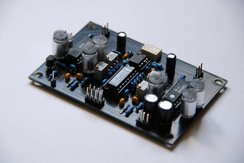
This PCB contains two of the famous SSM2044 24dB low pass filters with the necessary circuitry, additional LM13700 based Q linearization circuit and a tiny Omron micro relay for a software controlled (via gate out pins) bypass function. The layout is optimized for use with the AOUT_NG module, requiring the addition of a bipolar option when used with regular V/Oct sources like the original AOUT module.
As you can see, on my prototype I didn't take the size of 10nF Styroflex caps into account… New board size is 90x60mm instead of 80x50mm.
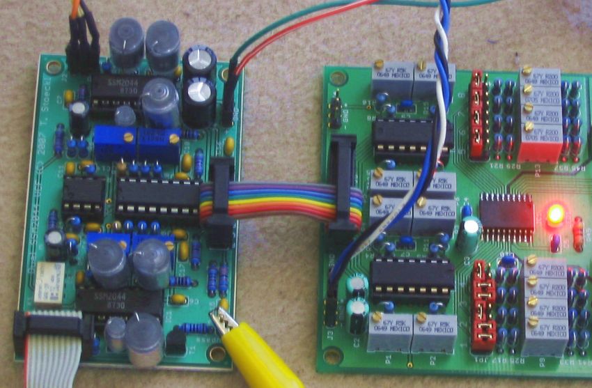
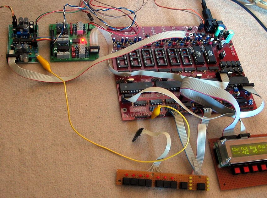
My prototyping setup, a MBSID V2 (MB-6582 base PCB) with 6581 SIDs and an AOUT_NG.
Here's a short audio demo: http://www.seppoman.de/stuff/SSMtest2.mp3
That's the “Bassline Demo2” default patch with SID filters turned off. First a sweep without resonance, then a bit of resonance and high resonance. Last a sweep up short before oscillation and down with oscillation (beware of high volume, the end is a bit distorted because of clipping 
TK made a very nice audio demo, too: http://www.midibox.org/forum/index.php/topic,11460.0.html
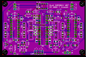
Layout and Schematic
Parts List
| Part | Value | Reichelt No. |
| C1,C2 | 220 uF | RAD 220/25 |
| C3,C4 | 10uF | RAD 105 10/63 |
| C5-C12 | 100nF | Z5U-2,5 100N |
| C13,C14 | 100pF | NPO-2,5 100P |
| C15-C18 | 470nF | Z5U-5 470N |
| C19-C24 | 10nF | STYROFLEX 10N |
| C25,C26 | 820pF | STYROFLEX 820P |
| D1 | 1N4148 | 1N 4148 |
| IC1,IC2 | SSM2044 | |
| IC3 | LM13700 | LM 13700 DIL |
| IC4 | TL072P | TL 072 DIP |
| K1 | G6K-2P | G6K-2P 12V |
| P1,P2 | 10k | 64W-10K |
| P3,P4 | 500 | 64W-500 |
| R1-R6 | 220 | METALL 220 |
| R7-R13 | 1k | METALL 1,00K |
| R14,R15 | 100 | METALL 100 |
| R16,R17 | 10k | METALL 10,0K |
| R18,R19 | 24k | METALL 24,0K |
| R20,R21,R24-R27 | 47k | METALL 47,0K |
| R22,R23 | 27k | METALL 27,0K |
| R28,R29 | 100k | METALL 100K |
| T1 | BC547 | BC 547C |
Total cost of all parts (without SSMs): about 11.50 Euros
nILS did a Reichelt Reichelt public shopping cart, thanks for that :)
Design
The SSM2044 is one of the classic integrated filter ICs, a 4-pole (24dB/oct) LP filter similar to e.g. the CEM3378/79. The sound is very rich and expressive (you heard the demos, right?). The big plus of the 2044 is that it is still widely available e.g. through eBay.
The main limitation of the 2044 for use in a digitally controlled CV application like MBSID/MBFM/MBCV… is that the response of the resonance input is exponential. that means, when controlled by a linear potentiometer or DAC, the usable range of control input is very limited, i.e. the lower third of values doesn't change very much, then there's a small area where you can really tweak the setting with good response, and in the upper third, the filter goes completely havoc.
In purely analog synths, this problem is adressed by using a negative log potentiometer that evens out this response curve. but when using CV for the resonance setting, this is not an option.
I've found a nice article from the 80ies where the CA3080 OTA is used to linearize the response. The CA3080 has recently become an obsolete part, you can still buy them, but they're getting quite expensive. So I adapted the design to work with the alternative LM13700 and tweaked the values until the behaviour was to my taste.
Another problem with the 2044 is that it produces some crackling noises when the CV changes are steppy (like the output of a DAC is). This was cured by adding a few capacitors to the control lines that low pass (smooth) these little steps.
The control summer found in all the documented designs on the web was removed. The frequency input of the 2044 expects an input of about -100..+100mV. The mentioned cirquit adapts that onto the standard V/Oct CV range. But this also means you would first need to adjust offset and gain of this cirquit to make the SSM input conform to that standard and then calibrate the output of your AOUT module to also comply with this standard. V/Oct is certainly important in a completely analog modular synth where several analog control sources are mixed and fed to that input, but in a situation where the AOUT is the only source, this conformity is not good for anything. So removing this stage of complexity reduces size and cost and takes away another level of necessary calibration.
The consequence of this is: If you want to use this module together with “non-AOUT” CV sources, you will need to add the control summer circuit externally (I'll publish a schematic for it soon). And, if you're using the module together with the classic AOUT module, you will need to add the bipolar option (as documented on the AOUT page) at least for both frequency channels (normally AOUT1 and AOUT3).
Filter Caps
It's possible to use different types of filter capacitors - above I listed the well respected Styroflex types. Before that I also tried ordinary ceramic capacitors and to my ears, the sound wasn't extremely different or worse with them. There are some subtle differences but as some people found it hard to find Styroflex caps, I just want to point out that these are not the only way to get a good sound :) - in general, it's a good idea to use capacitors with low tolerance (e.g. 5% or 2%). E.g. you could also try out Wima FKP-2 or MKS-2 capacitors (there are versions with several tolerances). The 820pF value is a bit harder to find than the 10nF value.
Another hint: I found out that with different capacitor types, the resonance response of the SSM does change. If with your capacitors, you aren't able to reach self-oscillation (or it sets in way too early), you can compensate by using a different value for R22 and R23. E.g. with the ceramic caps, I used 47k resistors.
Bypass Relay
The “bypass” function of the module in fact is an “activate” signal, i.e. the bypass pin expects a logic high signal (5V) to actually engage the filter (for both channels). This behaviour might seem a bit uncommon, but that way you can connect the pin to one of the gate out pins on either the Core or the (MAX525) AOUT module, so you can store the state of the filter together with your Bankstick patches. To use the bypass function on MBSID, set “#define DEFAULT_J5_FUNCTION 3”, recompile and upload, then connect one of core:J5's pins to J3 of the SSM module. Now you can turn the filter on and off by toggling the respective S#1…S#8 setting in the EXT menu.
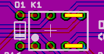
If you don't need this function, you can also solder two bridges instead of the relay (as shown below) and leave out R7, D1 and T1. That'll make the filter permanently active.
The Omron G6K-2P relay is available at several common places like Mouser, Digikey, Reichelt etc, but is a bit on the expensive side. If space is no issue, you could also use some short wires to solder in a different larger/cheaper/available 12V DPDT relay.
Calibration
(These instructions are for MBSID V2 in combination with an AOUT_NG).
For MBSID, the standard channel assignment is CV1 and CV3 for cutoffs, CV2 and CV4 for resonance. First calibrate the AOUT_NG to normal V/Oct like described on the NG page. Then in the EXT menu of the ensemble, turn on F2A (Filter cutoff/resonance routed to AOUT 1,3) and Iv1/Iv3 (invert AOUT 1/3). Then in the FIL menu of the ensemble, increase the Max param to FFF, turn off Log.
Calibration of the cutoff frequency is done on the AOUT_NG. Set both cutoff CV channels (CV1 and CV3) to bipolar mode. Now, the gain trimmers (P1..P8) set the cutoff range while the offset trimmers (P9..P16) shift that range up and down. For a start, now adjust these trimmers in a way that min. cutoff will set the cutoff very low and max cutoff will open the sound to the top.
Now, the resonance: Set both resonance CV channels (CV2 and CV4) to normal (not bipolar) mode. As explained above, the SSM2044 has an exponential Q response that needs to be compensated for usage with linear CVs. This means you want the Q to come up nicely without completely going mad at higher settings. The LM13700 does a transfer function similar to an audio compressor on the Q CV to make controlling high Q settings easier.
P1 and P2 on the SSM PCB adjust the overall gain, P3 and P4 set the breakpoint. For calibration, first set the breakpoint trimmers to about mid (use your multimeter), then adjust the gain to a point where Res=255 gives a good oscillation. Then adjust the breakpoint until Res around 240 does just not self-oscillate. To get both channels similar, it's a good plan to adjust both values a few times alternatingly and maybe compare the set trimmer values with a multimeter.
After the resonance is calibrated, you can now crank it up all the way to tune the cutoff frequency more exactly.

