Table of Contents
M16 MIDI Interface
Add 16 MIDI I/O to your Core, SPI Slave Interface with up to 16 UARTs(MIDI I/O), based on low-cost FPGA…
Features
- The FPGA internal clock works @88.67MHz.
- Fast 4 wires SPI in slave mode to control the board, 10Mb/s, 5V tolerant.
- Uses the default MIOS32_SPI_MIDI protocol, MIOS32 is ready-to-use with it.
- 16 UARTs on board, it's 16 MIDI ports.
- Each MIDI output has its own FIFO buffer of 1024 bytes, to queue the incoming MIDI from the SPI.
- Each MIDI output has its independent “Running Status”, with Disable/Enable Command from SPI.
- There's a 64 word(32bits) FIFO for out-coming messages from the board.
- 3 independents groups of 16 GPIOs, configurable and settable by SPI Command.
- Can be stacked under a dipBoardF4
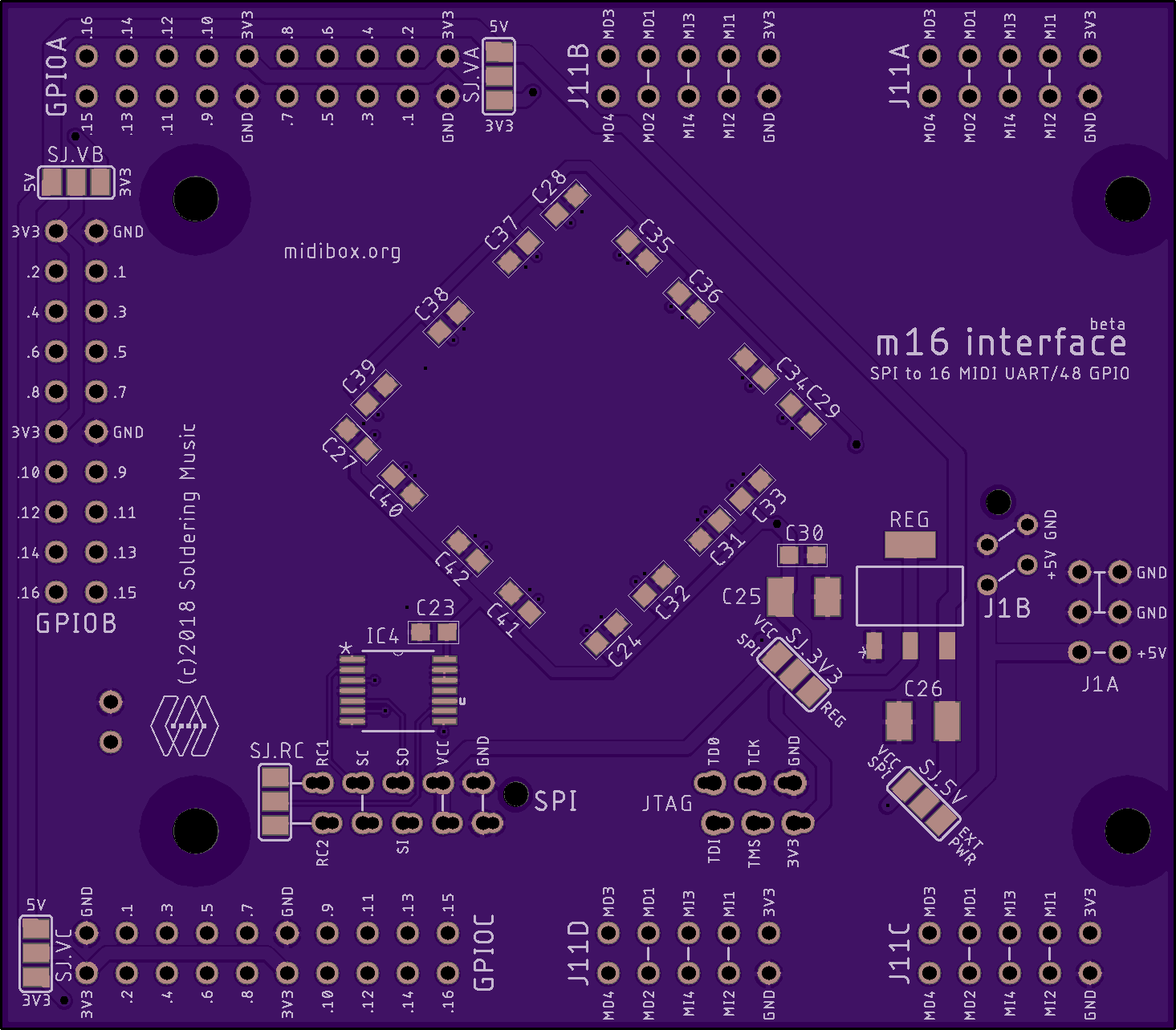
PCB
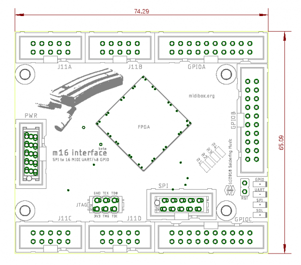
Dimension
BOM
version 1. Mouser BOM:toDo
| Qty | Value | Package | Parts | Mouser | Reichelt | Conrad | Other | Notes |
|---|---|---|---|---|---|---|---|---|
| Resistors | ||||||||
| 4 | 680R 5% | 0603 | R1, R2, R3, R4 | 667-ERJ-PA3J681V | Depends on Leds | |||
| Capacitors | ||||||||
| 3 | 10n | 0603 | C27, C29, C30 | 80-C0603C103M5RAC | ||||
| 15 | 100n | 0603 | C23, C24, C28, C31, C32, C33, C34, C35, C36, C37, C38, C39, C40, C41, C42 | 80-C0603C104Z3V | ||||
| 2 | 10u | SMC_B | C25, C26 | 647-F931C106MAA | ||||
| LEDs | ||||||||
| 4 | – | 0805 | LED.1, LED.2, LED.31, LED.4 | 755-SML-H12U8TT86C | ||||
| ICs | ||||||||
| 1 | LCMX02-7000 | TQFP144 | FPGA | 842-27000HC6TG144I | Speed grade 4 to 6, 3.3V! | |||
| 1 | 74LVC125 | TSSOP-14 | IC4 | 595-SN74LVC125APWR | ||||
| 1 | LD1117AS33TR | SOT223 | REG | 511-LD1117AS33 | ||||
| Connnector | ||||||||
| 1 | micro-match 2×2 | Male | J1B | 571-215464-4 | for stack | |||
| 1 | 2×3 | Male | J1A | 710-61200621621 | ||||
| 1 | micro-match 2×3 | Female | JTAG | 571-215079-6 or 571-2178710-6 (value line) | ||||
| 5 | 2×5 | Male | J11A, J11B, J11C, J11D, SPI | 710-61201021621 | ||||
| 1 | micro-match 2×5 | Male | SPI | 571-8-215464-0 | for stack | |||
| 5 | 2×10 | Male | GPIOA, GPIOB, GPIOC | 710-61202021621 | ||||
SPI Communication and protocol
This protocol is already implemented in MIOS32 as MIOS32_SPI_MIDI functions.
This is a SPI slave interface.
Host communication protocol is based on MMA Specification for USB communication.
MIDI data is carried in the packet in 32 bit MIDI Event. Most common MIDI messages are 2 or 3 bytes
packed into one MIDI Event.
Longer messages, generally System Exclusive messages are carried in multiple MIDI
Events. These MIDI Event provide a method to transfer MIDI messages with 32 bit fixed length messages to help
memory allocation. This also makes parsing MIDI events easier by packetizing the separate bytes of a MIDI
message into one parsed MIDI Event.
The first byte in each 32-bit MIDI Event is a sub-header containing a Port Index Number (4 bits) followed
by a Code Index Number (4 bits). The remaining three bytes contain the actual MIDI event. Most typical parsed
MIDI events are two or three bytes in length. Unused bytes are reserved and must be padded with zeros (in the
case of a one- or two-byte MIDI event) to preserve the 32-bit fixed length of the MIDI Event.
The Code Index Number (CIN) indicates the classification of the bytes in the and the number of bytes in the message. The following table summarizes these classifications.
//! this global array is read from MIOS32_MIDI to
//! determine the number of MIDI bytes which are part of a package
const u8 mios32_midi_pcktype_num_bytes[16] = {
  0, // 0: invalid/reserved event
  0, // 1: local command
  2, // 2: two-byte system common messages like MTC, Song Select, etc.
  3, // 3: three-byte system common messages like SPP, etc.
  3, // 4: SysEx starts or continues
  1, // 5: Single-byte system common message or sysex sends with following single byte
  2, // 6: SysEx sends with following two bytes
  3, // 7: SysEx sends with following three bytes
  3, // 8: Note Off
  3, // 9: Note On
  3, // a: Poly-Key Press
  3, // b: Control Change
  2, // c: Program Change
  2, // d: Channel Pressure
  3, // e: PitchBend Change
  1  // f: single byte

};
MIDI messages
Running status is never used, so all the messages are formed of all bytes. But the interface supports it, each MIDI Out can be individually set for that purpose.
Some examples
MIDI clock on port 7(SPIM0 to SPIM15)
MIDI message is 0xF8, cin = 0x5.
SPI message = 0x0000f875 (Less significant byte first)
    mios32_midi_package_t package;
    package.ALL = 0;
    package.cin = 0x5; // Single-byte system common message
    package.evnt0 = 0xf8; // MIDI Clock event status
    MIOS32_MIDI_SendPackage(SPIM7, package);
    // or directly
    MIOS32_MIDI_SendClock(SPIM7);
Note On on port 11
MIDI message is 0x90 0x2A 0x40, cin = 0x9.
SPI message = 0x402A90b9
    mios32_midi_package_t package;
    package.ALL = 0;
    package.cin = 0x9; // Single-byte system common message
    package.evnt0 = 0x90; // MIDI Note On event, channel 1
    package.evnt1 = 0x2A; // Note Number
    package.evnt2 = 0x40; // Velocity
    MIOS32_MIDI_SendPackage(SPIM11, package);
    // or directly
    MIOS32_MIDI_SendNoteOn(SPIM11, Chn1, 0x2A, 0x40)
System Exclusive on port 0
MIDI message is 0xF0 0x01 0x02 0x03 0x04 0x05 0xF7.
The stream will be divided in 3 packages:
SPI messages = 0x0101f004(SYSEX start), 0x05040304(SYSEX continues), 0x0000f705(SYSEX ends with one byte)
    mios32_midi_package_t package;
    package.ALL = 0;
    package.cin = 0x4; // Single-byte system common message
    package.evnt0 = 0xf0; // Start of Exclusive
    package.evnt1 = 0x01; // Data
    package.evnt2 = 0x02; // Data
    MIOS32_MIDI_SendPackage(SPIM0, package);
    package.evnt0 = 0x03; // Data
    package.evnt1 = 0x04; // Data
    package.evnt2 = 0x05; // Data
    MIOS32_MIDI_SendPackage(SPIM0, package);
    package.ALL = 0;
    package.cin = 0x4; // Single-byte system common message
    package.evnt0 = 0xf7; // End of Exclusive
    MIOS32_MIDI_SendPackage(SPIM0, package);
    // or directly
    u8 stream[7]={0xF0, 0x01, 0x02, 0x03, 0x04, 0x05, 0xF7};
    MIOS32_MIDI_SendSysex(SPIM0, (u8*)stream, 7);
Special command messages
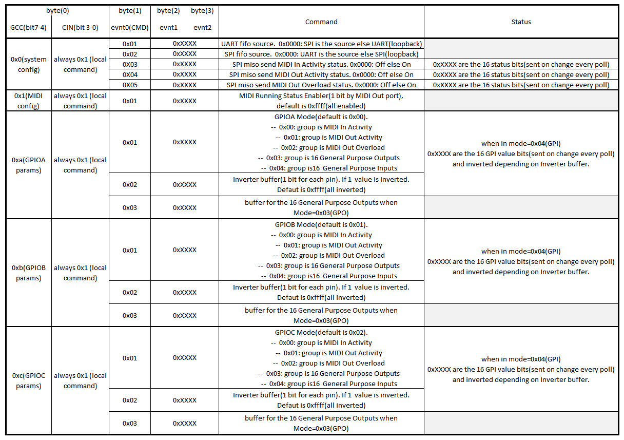
The m16 can receive some specifics commands and send back some status messages.
when CIN=0x1(local command), the m16 will parse the message as a command and apply the requested change.
- Port(Cable)value becomes Group Command Code(GCC).
- evnt0 is the command number(CMD.
- evnt1 and evnt2 are the value bytes.
List of the commands:
With System commands, you will be able to
- Put SPI or UARTs in loopback for testing purpose.
- Enable MIDI activity status messages over SPI(MISO).
There's only one MIDI configuration command, dedicated to UARTs TX(MIDI Out) Running Status enabler.
With GPIOx commands, you can configure and set the GPIO ports.
toDo
Some connection examples\\
In MIOS32
datasheet

