Table of Contents
MIDIbox Matrix - MIDI Matrix with 56 Inputs and 56 Outputs
This MIDIbox implements a 56-port MIDI matrix/router using a core board and an FPGA-based add-on board together with a set of break-out boards and modules that allow for physically placing your MIDI ports where you actually need them.
Overview
Because my Waldorf Midibay became too small for connecting all of my MIDI equipment I had to design my own MIDI matrix / programmable patchbay. The modular MIDIbox Matrix has up to 56 input and 56 output ports and can be scaled to your requirements.
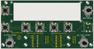
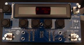
The prototype of the user interface (UI) already shows the main usage paradigm: a rotary encoder (on the lower right) is used to select the out port, thereafter the in port is selected with the rotary encoder on the left. This selection is confirmed by pressing the encoder. More changes to the current routing can be made, and when pressing the lower right rotary encoder, all changes are made effective and the routing is changed.
The buttons and encoder in the upper row, just below the display, belong to the SCS based menu system and will enter the config pages. Here, you can also load and save “patches” and configure the two mergers. The lower row of buttons doesn't do anything, except for one which is used for triggering a PANIC function, sending note off messages on all MIDI channels to all out ports.
MIDIbox Matrix features break-out boxes (BOBs) that give access to 4 in and 4 out ports at a time. These are connected via 9-pin serial cables to the main unit and are designed to be conveniently placed in the back of your rack, e.g. attached to the inner sidewall of a rack enclosure with screws or velcro tape. This means that instead of running 8 MIDI cables to the MIDIbox Matrix in order to connect four synths, you only need a single, cheap serial cable from your side rack to the center point of your matrix. I have successfully tried chaining five 5m long serial cables, bridging a total distance of 25m. It doesn't look as if this was the limit, though, and even larger distances between matrix and BOBs should be possible.
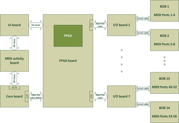
Two BOBs each connect to a single I/O board, which does all the level shifting and signal refreshing. Up to seven I/O boards can be attached to the heart of the MIDIbox Matrix, an FPGA-based switching and routing logic that is controlled via a core board such as the STM32 or the LPC17.
As the system is highly modular, it is possible to start with a low port count (4) and then increase the number of available ports by simply adding I/O boards and BOBs as needed. Fully loaded, i.e. offering 56 input and 56 output MIDI ports, the MIDIbox Matrix consists of
- 1x FPGA board
- 7x I/O boards
- 14x BOBs
plus a core board and the PCB holding the user interface.
BOB
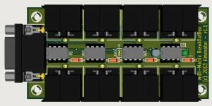
The BOB is designed to be mounted against the inner wall of a 19“ rack case. It connects via a shielded 9-pin serial cable to the main unit. On the BOB, the 9-pin DSUB socket is male, whereas a female DSUB socket is used on the main unit for protection against touching the pins (and the static-sensitive ICs on the I/O boards in the main unit). As the serial cables are male/female ones, a connection can easily be extended by chaining cables (but beware that there is a limit with respect to how many single cables you can chain, due to increased contact resistances).
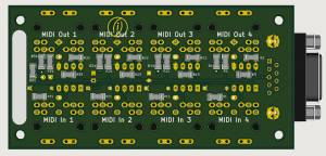
All MIDI in ports are located on one side, all MIDI out ports on the opposite side. They are clearly marked with the corresponding port numbers. I am using Formulor / Ponoko to laser cut the BOB's case, and the next one will therefore obviously be engraved 5…8, and so forth. A LED indicates whether the BOB is properly connected to the main unit. It discretely shines through the matte finished plexiglass case.
Like every MIDI device, MIDIbox Matrix features optocouplers on the MIDI in ports. Here, these optocouplers are located inside the BOB. This also means that the incoming MIDI signals are refreshed before they are passed on to the main unit. The optocouplers used here are standard 6N138 types and they are socketed for easy replacement (yes, optocouplers can break). Located on the soldering side of the BOB PCB are a number of SMD resistors in 1206 size. There is simply not enough real estate for more through hole components on this board.
Because I like the idea of recycling components that have barely been used in other, now obsolete equipment, the MIDI sockets can also be replaced with DIN sockets bearing different kinds of footprints and/or additional pins. I frequently use 8-pin DIN sockets de-soldered from old video equipment as they are fully compatible with the 5-pin MIDI plugs. Of course, the standard 5-pin MIDI socket footprint will fit here as well!
Most DIN sockets have two little holes on the bottom side which can be used to apply a pair of screws to secure them to the PCB from underneath. The BOB's PCB has the corresponding holes, so for minimum mechanical stress screw your sockets!
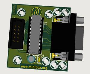
It is also possible to use the BOB directly together with the STM32F4 core board. A single BOB can replace two I/O boards. The only additional thing required for this to work is an adapter or cable from D-SUB to the polarized strip connector J11E.
Schematic
No surprises here, we are using the standard MIDI schematics for 5V signal levels, including optocouplers in the MIDI In section: this is the schematic of the BOB. The LED on this board is there to indicate that the BOB is active - it should light up if the BOB is properly connected to an I/O board.
Layout
The layout is governed by the basic design idea of having a compact little box that can easily be mounted in the back of a rack case. As a result it was necessary to use surface mounted resistors. However, this is no big deal - these are easily soldered after some practicing.
The total size of the PCB is 100mm x 50mm.
BOM
| Reference | Description | Package | Value | Quantity | Mouser | Reichelt |
|---|---|---|---|---|---|---|
| C1 | capacitor | C1V5 | 100µF | 1 | RAD 105 100/35 | |
| C2 | capacitor | C1 | 100n | 1 | Z5U-2,5 100N | |
| D1, D11, D21, D31 | diode | D3 | 1N4148 | 4 | 1N 4148 | |
| R1, R4, R5, R11, R14, R15, R21, R24, R25, R31, R34, R35, R50 | 1/4W resistor | SM1206 | 220 | 13 | SMD 1/4W 220 | |
| R2, R12, R22, R32 | 1/4W resistor | SM1206 | 1k | 4 | SMD 1/4W 1,0K | |
| R3, R13, R23, R33 | 1/4W resistor | SM1206 | 4k7 | 4 | SMD 1/4W 4,7K | |
| P1, P2, P11, P12, P21, P22, P31, P32 | MIDI socket | DIN 5 | 8 | MABP 5S | ||
| U1,U11,U21,U31 | optocoupler | DIP-8 | 6N138 | 4 | 6N 138 | |
| U1,U11,U21,U31 | IC socket | DIL-8 | 4 | GS 8 | ||
| LED1 | LED | 3mm | red | 1 | LED 3MM RT | |
| P9 | D-SUB 9pin male socket | DB9MC | 1 | D-SUB ST 09US | ||
| D-SUB 9pin serial cable 5m | 1 | AK 261 |
All resistors are placed on the backside of the PCB. All other components are sitting on the front!
STM32F4-to-BOB Adapter
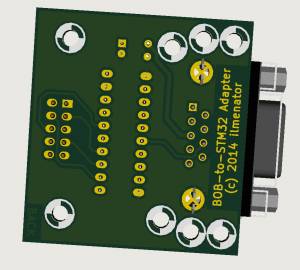
It is also possible to use a BOB directly together with an STM32F4 core board. Especially if you need the MIDI ports at some physical distance from the core board you should use the BOB-to-STM32 adapter. It provides an adapter from the IDC connector J11E on the core board to the DSUB 9pin connector on the BOB, as well as a line driver and level shifter for the MIDI out signals coming from the core board.
I/O Board
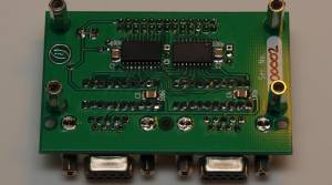
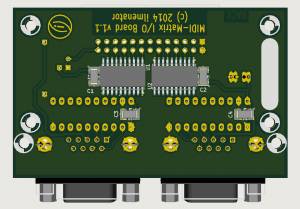
The I/O Board is the physical interface between the 5V MIDI signal level found in the BOB, and the 3.3V signal level required by the FPGA. This level shifting is done by one 74HCT541 and one 74LVC541 octal buffer / line driver, respectively. Especially the LVC version seems to be available in SMD only, hence a bit of SMD soldering is required here as well.
In addition to the 74xxx541 buffers, another pair of 74HC244 octal buffers / line drivers is used as input protection. These are socketed DIP ICs that can easily be replaced, should you ever connect an inappropriate signal to the DSUB jacks. Female DSUB sockets are used to protect the I/O Board against touching any I/O pins.
Each I/O Board handles 8 MIDI ins and 8 MIDI outs, i.e. it can connect to up to two BOBs.
Schematic
The v1.1 schematic of the MIDIbox Matrix I/O board can be downloaded here.
Layout
BOM
| Reference | Description | Package | Value | Quantity | Mouser | Reichelt |
|---|---|---|---|---|---|---|
| C1, C2, C3, C4 | capacitor | SM1210 | 100nF | 4 | X7R-G1206 100N | |
| C5 | polarized capacitor | radial | 470µF | 1 | RAD 470/16 | |
| C6 | polarized capacitor | axial | 10µF | 1 | AX 10/35 | |
| U1 | octal buffer / line driver / level shifter | SO20 | 74LVC541 | 1 | 595-SN74LVC541ADWR | |
| U2 | octal buffer / line driver / level shifter | SO20 | 74HCT541 | 1 | 595-CD74HCT541M96 | |
| U3, U4 | octal buffer / line driver | DIP-20 | 74HC244 | 2 | 595-SN74HC244N | 74HC 244 |
| U5 | voltage regulator | TO92 | TS2950 | 1 | TS 2950 CT33 | |
| P1 | IDC connector | 13×2 | IDC angled | 1 | WSL 26W | |
| P2, P3 | D-SUB 9pin female socket | DB9 | 2 | 649-D09S33E4PA00LF | D-SUB BU 09US | |
| U3, U4 | IC socket | DIL-20 | 2 | GS 20 | ||
| male/female spacer | M3 | 20mm | 4 | DA 20MM |
FPGA Board
The FPGA Board is the heart of the MIDIbox Matrix, as it performs the actual routing of MIDI ports. It is controlled via the DMA driven SPI port on the (STM32 or LPC17) core module, i.e. it connects to J8/J9, the serial DIN/DOUT ports.
The basic idea is rather simple: for each MIDI out port, a MIDI in port is selected whose signals should be forwarded. This selection is communicated to a 56(64)-to-1 multiplexer via a single 6(8)-bit shift register in the DOUT chain. Indeed, as we have 56 MIDI out ports, the corresponding DOUT chain is 56 shift registers long. However, thanks to the fact that this is “virtual” logic inside the FPGA, such long shift register chains do not present any signal integrity problems as witnessed in some other projects that use long SR chains. Any other DIN or DOUT shift registers you might want to use, e.g. for the user interface, must be located in the SR chain before this board.
Additionally, you can also merge MIDI streams. The FPGA board holds two PIC16(L)F88 based 2-to-1 MIDI mergers in parallel. Their inputs are served from any of the 56 MIDI in ports, and their outputs are forwarded to the STM32 core board for further MIDI stream processing. These streams can then be fed back into the Matrix and routed to any of the 56 MIDI out ports.
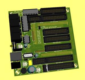 On the left is a rendering of the FPGA board created with KiCAD. This is the second generation v1.1 FPGA board which has a pair of MIDI I/Os, and an AC power plug (which can also be used to feed DC power). The board can loop through the USB signals from the Micro USB plug found on the STM32F4 Discovery (core) board to the outside world when the whole unit is mounted in an enclosure. The FPGA board connects to J8/J9 of the core board for DIN and DOUT chains, and to J11E for MIDI connectivity. The pair of MIDI I/O sockets on this board connects directly to MIDI I/O number 4 of the core board. In the future, it might be possible to remote control the MIDIbox Matrix via this MIDI port (yes, if my time allows…).
The FPGA board provides a range of power supply options. It can be fitted with a 5V and a 3.3V power section - the latter is obligatory if you want to use one or two PIC16LF88 MIDI mergers running at 3.3V. You can also feed them 5V, in which case the 3.3V power section can be omitted, as the FPGA gets its 3.3V from its own 3.3V regulator. Also, you might have a stable 5V supply already. Then, you can also omit the 5V section. You can also supply the core board from the FPGA board via J8/J9 and J11E.
The actual FPGA sits piggyback underneath the PCB, on a separate daughter board. An Altera Cyclone II device is used (EP2C8) which has a sufficiently large number of I/O pins. The daughterboard is from Waveshare, a Chinese manufacturer offering a wide range of development and evaluation boards.
Schematic
coming soon
Layout
coming soon
BOM
| Reference | Description | Package | Value | Quantity | Mouser | Reichelt |
|---|---|---|---|---|---|---|
| C8 | electrolytic capacitor | RM5, D10mm | 470µF | 1 | RAD FC 470/35 | |
| C9 | film capacitor | RM5 | 330nF | 1 | MKS-2 330N | |
| C10, C14* | electrolytic capacitor | RM2,5 | 47µF | 2 | RAD FC 47/25 | |
| C11, C15 | ceramic capacitor | RM2,5 | 100nF | 2 | Z5U-2,5 100N | |
| C12, C13 | ceramic capacitor | SM1210 | 100nF | 2 | ||
| R1 | resistor | SM1206 | 1k | 1 | SMD 1/4W 1,0K | |
| R2 | resistor | SM1206 | 4k7 | 1 | SMD 1/4W 4,7K | |
| R3 - R5 | resistor | SM1206 | 220 | 3 | SMD 1/4W 220 | |
| RR1, RR2 | resistor network | SIL6-5 | 10k | 2 | SIL 6-5 10K | |
| U1, U2 | microcontroller | DIP-18 | PIC16F88 | 2 | PIC 16F88-I/P | |
| IC sockets | DIP-18 | 2 | GS 18 | |||
| U3 | voltage regulator | TO-220 | 5V DC, 1A | 1 | TSR 1-2450 | |
| U4* | voltage regulator | TO-220 | 3,3V | 1 | LF 33 CV | |
| U5 | optocoupler | DIP-8 | 6N138 | 1 | 6N 138 | |
| P1, P2 | female header straight | 2mm | header 25×2 | 2 | MPE 156-3-050 | |
| P3 | female header straight | 2mm | header 16×2 | 1 | MPE 156-3-032 | |
| P4, P5 | IDC connector | 5×2 | IDC | 2 | WSL 10 | |
| P6 | power connector | Cannon plug-type socket | 1 | HEBW 21 | ||
| P7* - P9 | power header | 2,54mm | 3 | PSS 254/2G | ||
| P10 - P16 | IDC connector | 13×2 | IDC | 7 | WSL 26 | |
| P17, P18 | MIDI socket | DIN-5 | 2 | MABP 5S | ||
| P19 | SIL header | 3-pin | 1 | |||
| J1 | USB socket | type B | 1 | USB BW | ||
| J2 | USB socket | type A vertical | 1 | USB AG | ||
| JP1 - JP4 | SIL header | 2-pin | 4 | |||
| D1 | bridge rectifier | round | B40C1500 | 1 | B40C1500RUND | |
| D2 | diode | DO35 | 1N4148 | 1 | 1N 4148 | |
| Q1 - Q5 | transistor | SOT-23 | BSS138 | 5 | BSS 138 SMD |
* U4, P7, C14 can be left out if the mergers (U1, U2) are 5V powered.
User Interface
The layout of the user interface (UI) is based on the MIDIbox SCS, two dedicated clickable encoders for in- and out-port selection, and an additional PANIC button. It fits in the frontpanel of a standard 2U rack case, offers a 2×24 display for feedback, and 5 buttons along with an encoder for navigating the menu system.
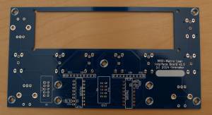
A second generation PCB as pictured above has been ordered and tested to work. This PCB can also be used with other projects involving an SCS, e.g. the MIDIbox NG. Both, my favourite switches from Marquardt (6425 series), as well as the E-Switch TL1100 series (see e.g. MB SEQv4) can be used.
Schematic
The v1.0 schematic of the MIDIbox Matrix UI/SCS board can be downloaded here.
Layout
As with any user interface board, form follows function here. Switches and encoders are mounted on the front, everything else sits on the back of the PCB. There are mounting holes and a cutout for a 2×24 character display right above the four “soft” buttons. For the MIDIbox Matrix, SW7 (on the far right) is not used, but your project might need it.
The total size of the PCB is 150mm x 80mm.
BOM
| Reference | Description | Package | Value | Quantity | Mouser | Reichelt | soselectronic |
|---|---|---|---|---|---|---|---|
| C1, C2 | capacitor | RM2,5 | 100nF | 2 | Z5U-2.5 100N | ||
| U1, U2 | shift register | DIP-16 | 74HC165 | 2 | 74HC 165 | ||
| P1, P2 | IDC connector | 5×2 | IDC | 2 | WSL 10 | ||
| RR1, RR2 | resistor network | 10-9 | 10k | 2 | SIL 10-9 10K | ||
| ENC1 - ENC3 | rotary encoder with switch | 3 | STEC12E08 | ||||
| SW1 - SW7 | tact switch | 12mm | E-Switch | 7 | 612-TL1100 | ||
| switch cap | C&K Components | 7 | 611-PEBK | ||||
| SW1 - SW7 | push switch | Marquardt 6425.0101* | 7 | 979-6425.0101 | TASTE 6425.0101 | 1325 | |
| key cap | Marquardt 826.000.011 | 16x16mm | 7 | TASTE S 826 (red!) | 1489 |
* Button caps for the Marquardt's usually have to be ordered separately - these should be the 16x16mm types, not the 19x19mm!
Note that you will obviously only need one type of switch! Not listed here are the encoder knobs, but any push-on knob for D-type shaft should work.


