Table of Contents
MIDIbox SCS Standard Control Surface module
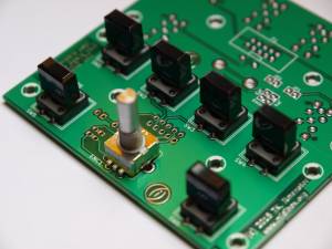
The SCS module implements a standard user interface that is available as a module in the MIOS codebase. It goes nicely with a 20x character LCD and connects to J10 on the core board. An application example can be found in tutorial #027.
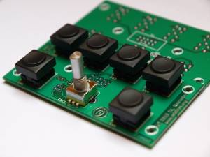
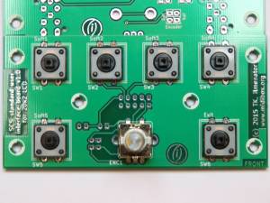
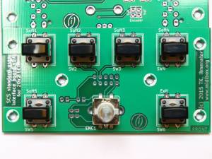
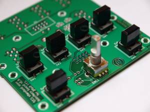
The PCB I have designed can accommodate three different types of switches: my favourite switches from Marquardt (6425 series), TK's favourites from ITT Schadow (D6 series) available at Reichelt, and the E-Switch TL1100 series (see e.g. MB SEQv4) can be used.
Schematic
The v1.0 schematic of the MIDIbox SCS board can be downloaded here.
PCB
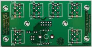
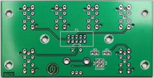
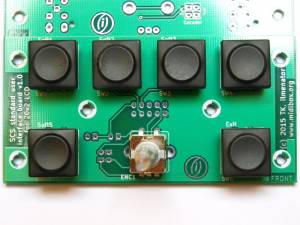
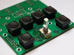
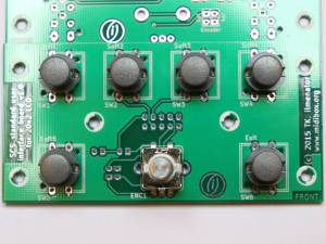
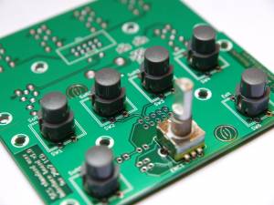
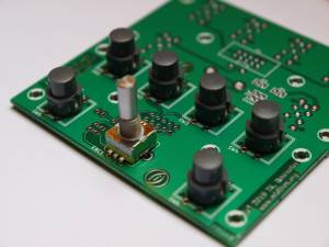
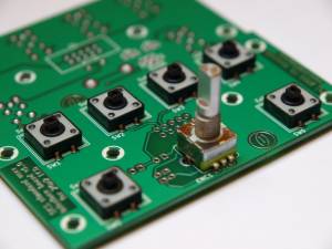
As with any user interface board, form follows function here. Switches and encoder are mounted on the front, everything else sits on the back of the PCB. There are mounting holes all over the PCB, SW5 (on the lower left) doubles the encoder switch if needed, e.g. to act as a “fast” button.
Jumper JP1 activates SW5, JP2 activates the encoder switch when closed. You can use both in parallel if you want to. Jumpers JP3 and JP4 determine the direction of the encoder. These have to be closed in one of the two possible configurations, otherwise the encoder will not be connected to P1.
The total size of the PCB is 97mm x 49mm.
Where to buy?
If you are interested in buying this, send a personal message (PM) to user ilmenator over at the MIDIbox forum (you have to register to be able to send PM). As of September 2021, I have PCBs available for 4,50€ each.
Switches
At least three different switches can be used.
Marquardt 6425 series
ITT Schadow D6 series
E-Switch 612-TL1100 series
E-Switch 612-TL1100 series with C&K Components switch caps
Encoder
I have chosen to follow the ALPS STEC11 type encoder pinout, as these seem to be pretty common, at least here in Europe. The data sheet is here. The block of jumpers JP3 and JP4 must be closed in parallel, either horizontally or vertically, and determines the turning direction of the encoder. These jumpers basically exchange where the pins A and B of the encoder go to. The middle pin of the encoder has to be the common C pin.

