MIDI8
Simple extension for MIDI in and out (similar to two MIDIO boards) that makes a special accommodation for the BLM port.
Schematic
See here for MIDIO. The LED activity circuits were omitted for space/complexity reasons; anyway they are often continuously lit when a MIDI clock is running.
The BLM port deserves special mention. MIDI I4 and O4 can be built as normal DIN5 connectors, or both can be combined into one DIN8 in the same location on the PCB. A more common DIN8 socket layout is used. If a BLM or other device needing bidirectional MIDI is envisioned, then the adjacent “I4” DIN position is redundant. In this case, the DIN8 can be used as a power supply input. For example, a “+5V” supply that is actually a higher voltage could be used and sent down the BLM cable to account for voltage drops and regulated therein.
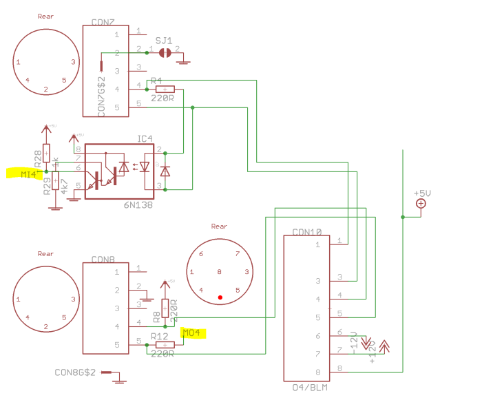
BLM port with Core connections to MI/O4 shown.
There is provision to use two normally unconnected pins of the DIN8 in the “I4” position to provide bipolar supply rails, e.g. +/-12V. These are connected to the left-hand Eurorack-style 2*5 header (red stripe down).
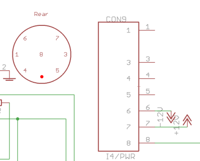
Connector I4. Pin 8 can be connected to +5V or to a higher voltage for downstream regulation.
If I4 is used as a power input and/or a BLM is connected, the following should be considered:
- to connect the BLM +5V to the USB +5V, solder a jumper wire below J3 as indicated.
- for other BLM power options, leave J3 open.
- +5V for the BLM can also be supplied on header J3. For instance, by wiring directly to the wcore_usb headers rather than relying on thin ribbon cable and IDCs.
- +5V for the BLM (or a higher voltage to be later regulated) can come in on connector I4, pin 8 (the middle pin of the plug). If I4 is used in this way, ensure solder jumper SJ1 on the rear of the board is closed.
- I4 can be used to supply (bipolar) power into the case on pins 6 and 7 as indicated. This supply is also forwarded to the same pins on the BLM port (O4). Close SJ1 too.
- If I4 is used as a normal DIN5 MIDI input, leave SJ1 open (MIDI inputs do not have 0V/ground connected).
BOM v1.0
Please find the current BOM on http://midiphy.com. The table below is depreciated and will not be updated.
| Type | Qty | Value | Package | Parts | Mouser | Reichelt | Conrad | Other | Notes |
|---|---|---|---|---|---|---|---|---|---|
| Resistors | |||||||||
| 12 | 220R 5% | THT | |||||||
| 4 | 1k 5% | THT | |||||||
| 4 | 4k7 5% | THT | |||||||
| Diodes | |||||||||
| 4 | 1N4148 | THT | |||||||
| ICs | |||||||||
| 4 | 6N138 | DIP 8 | |||||||
| IC sockets | |||||||||
| 4 | DIP8 | ||||||||
| Headers | |||||||||
| 1 | 1*3 | male | J3 | ||||||
| 4 | 2*5 | male | J1, J2 | ||||||
| Sockets | |||||||||
| 8 (6) | DIN5 | female | CON1-6(8) | 806-KCDX-5S-S2 | |||||
| 0 (2) | DIN8 | female | (CON9-10) | 806-KCDX-8S-S2-PS | |||||
| Hardware | |||||||||
| 3 | M3 spacer | optional, suggest to panel mount | |||||||
| 2 | M3 PCB mount | 534-7695 | |||||||
Versions
v1.0: first release.
Assembly
Building is straightforward with all part values indicated. Start with the flattest components (resistors and diodes, IC sockets) and work up to the higher ones. Ensure the DIN sockets are snug against the PCB before soldering all of the pins!
If a BLM connector is used, consider how it will be powered (see above). Don't close the jumper below J3 unless you're using the USB +5V to power it. E.g. if you had connected a higher voltage to pin 8 on I4 and closed the jumper, then the USB power would fight with the external one and let out the magic smoke.
License
Currently the design is © 2017 antilog devices with all rights reserved; all documentation is CC BY-NC-SA 3.0.