northernlightx
NorthernLightX's Projects
My Own User Projects
<box 48% round left green|Power Supply>
- Overview
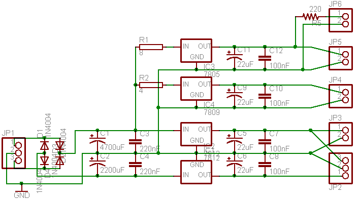
- This is a general purpose Power Supply Unit (PSU) which outputs +5v, +9v, +12v and -12v, designed by Mendelt and myself. The main reason I wanted a PSU like this was that every C64 PSU brick I touched died on me within a few days. Instead of messing with years-old stuff, I would rather have something new.
- In addition to the C64 PSU, this schematic provides an additional -12v rail, which can be used for a variety of things such as the OPL3 board and/or external filters.
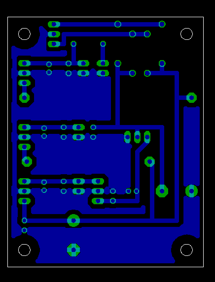
- The current board layout places all positive regulators in line, so that they can be heatsinked together. The negative regulator has a different pinout and the metal slab is NOT ground like on the positive regulators, so if you want to heatsink it be extra careful and take isolation precautions.
- The measured AC ripple on the outputs is very low, never more than 0.1mV, which I believe is very good (no hum on audio lines). I do not know how it compares to the Optimized PSU schematic with the C64 PSU brick, and I would like to have some test results for comparison.
- Theory of operation
- The big resistors will dissipate an amount of Volts equal to the amount of Ohm they're rated for, at a current of 1 Ampere. If the current is less than 1A they will dissipate less, but the regulators will be stressed less too, so this is exactly what is wanted. The power out of the mains can be plus or minus 10% of the specification (115V or 230V). Let's assume it is -10%, as it is in my house. So, instead of the 12V the trafo delivers at 230V, it in fact delivers 10,8V (12V - 10%). When rectified and filtered, the voltage becomes 10,8V * 1,41 = about 15,23V. this is perfect for the 7812 and 7912, so far so good.
- If we assume (for simplicity's sake) that there's a load of 1A behind the 7805, the resistor R1, which is rated for 8 Ohm, will dissipate 8 Volts. The voltage after the rectifier is 15,23V, so there will only be 7,23 V left, perfect for the 7805. At the 7809 it's the same story, 15,23V - 4V is 11,23V. The load after the 7809 will in most cases be nowhere near 1A, but it is nice to know that every rating has been thought out. These numbers though are the best case scenario.
- If for example the mains is not -10%, but +10% of specification, the voltage before the 7812 and 7912 is 12V * 1,1 * 1,41 = 18,61V. Not something to worry about if you got a decent heatsink on them. But for the 7809 an 7805 it's a different story, they will be fed with 18,61V - 4V = 14,61V and 18,61V - 8V = 10,61V. This is why heatsinks on all regulators are advisable.
- Reichelt Partlist
| Description | Qty | Part # | Price | Total |
|---|---|---|---|---|
| Voltage Regulator 7805 | 1 | uA 7805 | 0.17 | 0.17 |
| Voltage Regulator 7809 | 1 | uA 7809 | 0.17 | 0.17 |
| Voltage Regulator 7812 | 1 | uA 7812 | 0.17 | 0.17 |
| Voltage Regulator 7912 | 1 | uA 7912 | 0.17 | 0.17 |
| Resistor 220 Ohm | 1 | 1/4W 220 | 0.10 | 0.10 |
| Resistor 4 Ohm 5W | 1 | 5W AXIAL 3,9 | 0.29 | 0.29 |
| Resistor 8 Ohm 9W | 1 | 9W AXIAL 8,2 | 0.36 | 0.36 |
| Polarised Capacitor 4700 uF | 1 | rad 4700/35 | 1.00 | 1.00 |
| Polarised Capacitor 2200 uF | 1 | rad 2200/35 | 0.46 | 0.46 |
| Polarised Capacitor 22 uF | 4 | rad 22/35 | 0.06 | 0.24 |
| Ceramic Cap 220 nF | 2 | Z5U-2,5 220n | 0.13 | 0.26 |
| Ceramic Cap 100 nF | 4 | Z5U-2,5 100n | 0.06 | 0.24 |
| Diode 1N4008 | 4 | 1N 4008 | 0.02 | 0.08 |
| 1-row SIL Headers (about 14 pins) | 1 | STIFTL. 40G | 0.18 | 0.18 |
| Ringkern/Toroid Trafo 2x12V 50VA | 1 | RKT 5012 | 12.30 | 12.30 |
| Total | 16.10 | |||
- Note 1: Heatsinking of the 78xx regulators is a must. It is possible to create a heatsink from a piece of aluminium that you attach to all 3 regulators.
- Note 2: The 7912 regulator has a different pinout than the 7812, the metal slab is 12V in, so take the necessary precautions if you want to heatsink it!
- Optional parts (not necessary but very handy!)
| Description | Qty | Part # | Price | Total |
|---|---|---|---|---|
| Female Power plug | 1 | KES 2 | 0.69 | 0.69 |
| Fuse holder | 1 | HALTER 10,3×38 | 2.10 | 2.10 |
| OR Combined Power plug + Fuse | 1 | KES 1SI | 1.35 | 1.35 |
| Power switch | 1 | DS 059 RT | 1.55 | 1.55 |
| 1-row FEMALE SIL Headers | 1 | BL 1X20G8 2,54 | 0.34 | 0.34 |
- An LED to indicate if power is on or off might also be a good idea.
- Pictures

- Links to the Eagle files
http://home.quicknet.nl/qn/prive/alex.span/midibox/MBHP_PSU.brd http://home.quicknet.nl/qn/prive/alex.span/midibox/MBHP_PSU.sch
- Link to the original forum post
http://www.midibox.org/forum/index.php?topic=6374 </box>
<box 48% round right green|Distortion for guitar>
- Overview
- My goal was to design a very versatile distortion unit for my friend Malcolm. When talking about making music, he told me he was a bit dissatisfied with his digital effect unit; it was just not easy enough to operate. As with the PSU, Mendelt helped me a lot with making the schematics, and we are definitely going to adapt the schematics for synthesizer use.
- Sound tweaking options
- Drive potentiometer (1st Opamp)
- Clipping potentiometer adds clipping to the standard opamp overdrive
- Clipping switch selects between soft and hard clipping
- Big Muff tone section with potentiometer
- Level potentiometer (2nd Opamp)
- Technical details
- Imput impedance of 1MOhm
- Clipping makes use of diodes which can be picked by the builder
- Partlist
- 1 dual opamp (IC1)
- 2 electrolytic capacitor 100uF (C3, C8)
- 2 electrolytic capacitors 1uF (C9, C10)
- 2 film capacitors 100nF (104, C1, C6)
- 1 film capacitor 22nF (223, C4)
- 1 film capacitor 10nF (103, C5)
- 1 ceramic capacitor 470pF (C2)
- 1 ceramic capacitor 220pF (C7)
- 2 potmeters 100K LIN (R3, R7)
- 1 potmeter 100K LOG (R9)
- 1 potmeter 10K LIN (R5)
- 2 resistors 1M (R1, R2)
- 2 resistors 47K (R8,R12)
- 1 resistor 39K (R6)
- 3 resistors 10K (R10, R13, R14)
- 2 resistors 1K (R4, R11)
- 2 diodes (D1, D2)
- 2 6,3mm mono jack plugs (X1, X2)
- 1 DPDT switch (bypass, S1)
- 1 SPST switch (clipping, S2)
- It is also possible to use a 3PDT switch and an LED to indicate the position of the bypass switch, instead of the listed DPDT switch, I used this and it is a nice addition.
- A small 2-pole on/off toggle switch to turn off the battery can be a nice addition.
- What the parts really do
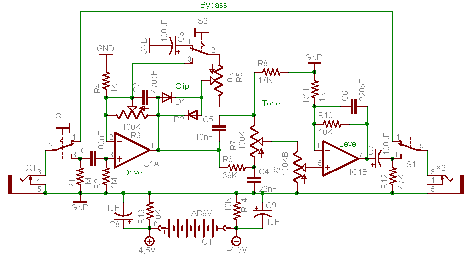
- X1 and X2 are the input and output jacks
- S1 is the bypass switch
- S2 switches between soft and hard clipping.
- R1 acts as a click-preventing resistor. It cuts out all clicks and other unpleasent sounds from the signal.
- C1 filters DC voltage from getting into your instrument.
- R2 makes sure the potential at the input of IC1a is always equal to GND.
- IC1 is the dual opamp.
- R3 is the Drive potmeter, and controls the amount of feedback through the first opamp.
- R4 and C2 form a 33KHz lowpass filter that cuts out all high frequency noise.
- D1 and D2 are clipping diodes.
- C3 protects the first opamp from shorting when hard clipping the signal.
- R5 is the Clipping potmeter, and turns from clipping to standard overdrive.
- R6, R8, C4 and C5 form lowpass and highpass filters.
- R7 is the Tone potmeter and controls the frequency that the tonestack operates on.
- R9 is the Volume potmeter and controls the amount of signal fed into the second opamp.
- R10 and C6 form a lowpass filter for the amplification frequency of IC1b.
- R10 and R11 also set the fixed gain for the second opamp to 11.
- C7 prevents DC voltage from the second opamp from reaching the output jack.
- R12 keeps the output at 0v when there's no signal going through the circuit.
- R13, R14, C8 and C9 pull GND to half of the supplied voltage, to be able to use the bi-powered opamp with a unipolar supply like a 9v battery.
- The circuit can be powered with anything ranging between 4 and 30 volts DC, but 9v is preferred to preserve the designed sound characteristics (lower voltage makes the opamps distort earlier, higher voltage provides more headroom).
- Any dual opamp can be used, just watch the pinout. I used a TL082 which has a low current drain, excellent for battery operated devices such as a guitar stompbox.
- The clipping diode section can be populated by a wide variety of diodes. Often used clipping diodes include Germanium diodes 1N34 and 1N270, Silicium diodes 1N914 and 1N4001 and LEDs. It is also possible to use JFETs or MOSFETs as clipping diodes.
- For assymetrical clipping use different diodes on both sides, or stack 2 diodes on one side and only one on the other. I used 1N34 and 1N4001. If you use assymetrical clipping you should place an extra 100nF capacitor between R7 and R9. This is to prevent offset DC voltage from the assymetrical clipping to damage the second opamp.
- Pictures

- Link to the Eagle file
http://home.quicknet.nl/qn/prive/alex.span/distortion/distortion.sch
- Link to the original forum post
http://www.midibox.org/forum/index.php?topic=9612
- Links to websites which have much info on various distortions and other guitar effects
http://www.generalguitargadgets.com/richardo/distortion/ http://www.runoffgroove.com/articles.html </box>
northernlightx.txt · Last modified: 2016/06/21 10:28 by psykhaze