Table of Contents
wCoreF4 PCB
This is the carrier board for the Waveshare Core407v. It performs breakout functions of all of the standard ports as per the design based on the STM32 Discovery.
Schematic
The circuit is mostly identical to what was drawn previously. The following parts are different:
USB entry (J1)
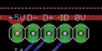
This header supplies +5V, 0V, USB data and the ID state. Normally it will be connected to the USB module by a short cable.
Extended port (J16E)
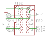
The original J16 functionality is preserved, but extra pins are available on an IDC16 header. These include the Reset signal and pins normally controlling LEDs. This header is normally connected to the RES-SD module.
User button (JPA0)
This jumper replaces the “bootloader” functionality of the Discovery board's blue button. It could be wired to an external panel control if needed.
BOM v1.0
Please find the current BOM on http://midiphy.com. The table below is depreciated and will not be updated.
| Type | Qty | Value | Package | Parts | Mouser | Reichelt | Conrad | Other | Notes |
|---|---|---|---|---|---|---|---|---|---|
| Resistors | |||||||||
| 1 | 330R 5% | THT | R102 | ||||||
| 1 | 560R 5% | THT | R33D | ||||||
| 3 | 1k 5% | 1206 | R33A,B,C | ||||||
| 2 | 1k 5% | THT | R11, R13 | ||||||
| 2 | 2k2 5% | THT | R7A, R8A | ||||||
| 2 | 2k2 5% | 1206 | R7B, R8B | ||||||
| 1 | 10k 5% | THT | R12 | ||||||
| 1 | 220k 5% | THT | R101 | ||||||
| Pots | |||||||||
| 2 | 10k | 6*5mm vert | P1, P2 | ||||||
| Capacitors | |||||||||
| 3 | 100n | 1206 | C1A, C1B, C2 | ||||||
| Diodes | |||||||||
| 1 | 1N4148 | THT | as marked | ||||||
| Transistors | |||||||||
| 1 | BC337 | TO-92 | T1 | ||||||
| ICs | |||||||||
| 2 | 74HCT125 | SOIC | IC1A, IC1B | 595-SN74HCT125DR | Ensure HCT | ||||
| 1 | 74HC595 | SOIC | IC2 | ||||||
| Headers | |||||||||
| 2 | 1*2 | male | |||||||
| 1 | 1*3 | male | |||||||
| 1 | 1*5 | male | J1 | or wire directly | |||||
| 9 | 2*5 | male | |||||||
| 3 | 2*8 | male | |||||||
| 2 | 2*25 | female | solder before male headers | ||||||
| Hardware | |||||||||
| 4 | M3 spacer | 8mm(?) | |||||||
| MCU breakout | |||||||||
| 1 | Waveshare Core 407v | ||||||||
Versions
v1.2: general release. Changes:
- The USB board is now combined with the wCore. It can be used as is or broken apart and the USB reconnected with wires, a 2.54mm header or a 10-pin Micro-MaTch connector.
- Resistors R7B1-4 were renamed properly to R33A-D. R33D should have a different value (560~820R) than R33A/B/C (1k). Using longer cables on J15A/B and a smaller resistance for R33D could lead to displays not initialising properly.
- There is a circular silkscreen mark that aligns with the same mark on the Waveshare breakout.
v1.0: first release.
Assembly
The following build order is suggested:
- R7B1-4 (1k 1206) and located near J15_S on the top side
- R7B and R8B (2k2 1206) on the bottom side
- C1A, C1B and C2 (100n 1206) on the bottom side
- IC1A, IC1B (74HCT125) and IC2 (74HC595) on the bottom side
- Top-side THT resistors R7A 2k2, R8A 2k2, R11 1k, R12 10k, R13 1k and diode
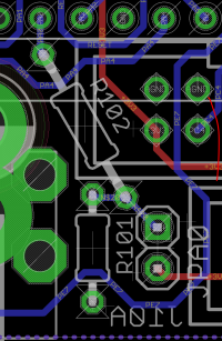
- Bottom-side THT resistors R101 220k, R102 330R
- Top-side transistor and trimpots
- Bottom-side JPA0 header
- Bottom-side 2*25 pin female headers
- for a SEQ v4+ build, consider omitting headers J4B, J5A, J5B, J10A, J10B and J18
- Top-side male headers, except for J1
- Solder J1 in conjunction with the USB module
- Mounting brackets if needed
Connecting the Core407v breakout
- Checking the Waveshare board, you will see that there is a real-time clock crystal and associated caps connected across PC14 and PC15. I think it's best to remove these parts so they don't interfere with normal operation. Clip the leads of the crystal and desolder the part if you like. The caps should come off quite easily with a soldering iron tip heating both pads. Don't leave any solder bridges!
- The Core 407v board plugs in on the bottom side with the the USB mini connector located below J4A.
- Explained another way: the JTAG header should be somewhat aligned with the 2-pin CAN header J18:
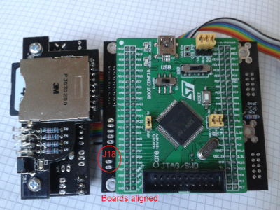
- The 407v board should not protrude past the edge of the PCB.
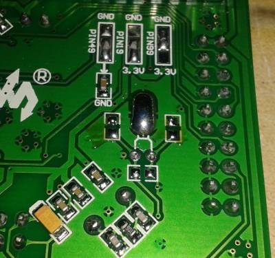
- Remove the OTG jumpers “FLG,” “VBUS” and “PWR OUT.” USB won't work properly with these closed.
- I believe that the correct state of the BOOT CONFIG switch should be set to “FLASH”
- There's another switch to select the +5V power. It should be set to “USB” when flashing the board using the USB mini connector as a power source, but for our purposes set it to “PWR 5V”.
License
Currently the design is © 2017 antilog devices with all rights reserved; all documentation is CC BY-NC-SA 3.0.