Table of Contents
wCoreF4
This is a cross-grade of the STM32F4 Core based on the Core407v breakout board from Waveshare. There are other versions of MCU breakouts, but the Waveshare one seems quite a reputable source with decent distribution and documentation.
Pros
- Slightly smaller footprint
- (Almost) all connectors on same face
- Proper USB A and B ports
- Footswitch/gate 3.5mm jack
- Hardware host/slave switch
- LEDs on the panel
- Reset button on the panel
- User button on header
- More mounting options available (e.g. panel mount including USB)
- 1A 3v3 regulator
- Possibility for external Vref (for AIN)
Cons
- Similar height to Disco version (could cut off headers etc.)
- Lacks ST-LINK and requires a (cheap) programmer or a Discovery module
- No mounting holes on MCU breakout
- Requires SMT soldering (wide pitch)
Sub parts
The Core is split over three PCBs:
The MIDI interfaces were also redesigned:
Build instructions are found on the appropriate pages.
MCU module
The actual MCU module is available from several sources:
Burning the bootloader
The MCU module has a USB port, but direct programming would only be possible with a USB-UART programmer. It would also require a different bootloader protocol. Instead, we make use of SWD functionality. The MCU module has a typical JTAG/SWD header and these pins are also available on the two 2*25 header rows.
I believe that the BOOT CONFIG switch should be set to SYSTEM, although I think this is more relevant for flashing through UART rather than SWD.
Option 1: ST-LINK clone
These are readily available from eBay and other sellers for typically <$10. You only require one programmer to flash as many modules as needed.
Option 2: use a Discovery module
The Discovery module (even if connected to a MIDIbox Core) can be used for programming. To do so, remove the two CN3 jumpers labelled ST-LINK/DISCOVERY. This disconnects the SWD interface from the STM32F4 MCU on the Discovery board:

Note that pin 1 of the 6-pin SWD interface on CN2 of the Discovery board only detects the voltage of the target. Thus the most foolproof method of flashing is to connect a mini USB cable to the 407v board and set the power switch to USB. This ensures that the board is always powered up when programming. After the bootloader is burned in, the 407v board can be installed in the wCore PCB through the two 2*25 headers.
Flashing over SWD
The following five connections should be made with DuPont cables:
- 3v3
- 0V/ground
- DIO
- CLK
- RESET
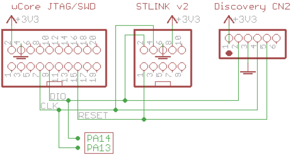
Of course, only one programmer should be connected to the 407v board!
After that, follow the instructions for the initial flash of a Discovery module.
If the JTAG/SWD header of the 407v board had to be removed and the MCU required re-flashing, it's possible to do so using the named pins on the 2*25 header.
License
Currently the design is © 2017 antilog devices with all rights reserved; all documentation is CC BY-NC-SA 3.0.